Hello! Welcome to the Bib build bibld guide (v2). Bib is quite a simple build, and fairly beginner friendly. This updated build guide involves less trimming of pins, which makes it a little easier - but is 'electrically' the same. If you want to check out v1, it is here.
You will need: a soldering iron, side cutters, a bib kit, and a little patience.
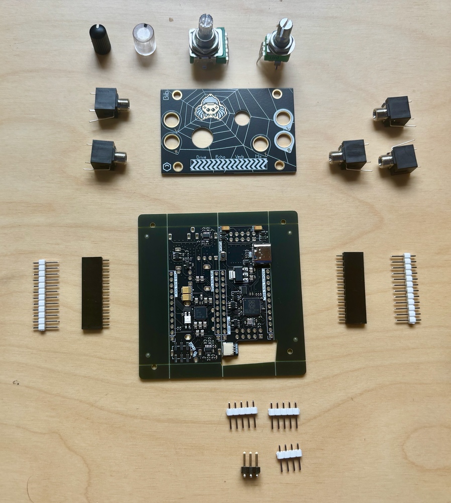
Below are most of the parts of the Bib kit, with the exception of the Eurorack power cable, mounting hardware, and for no reason other than my forgetfulness, a small 4 pin SMD socket that we will meet shortly:
Video guide by Meska
Plinky community member extraordinaire Meska has created a step by step video tutorial for soldering Bib.
The headers - a nice warmup
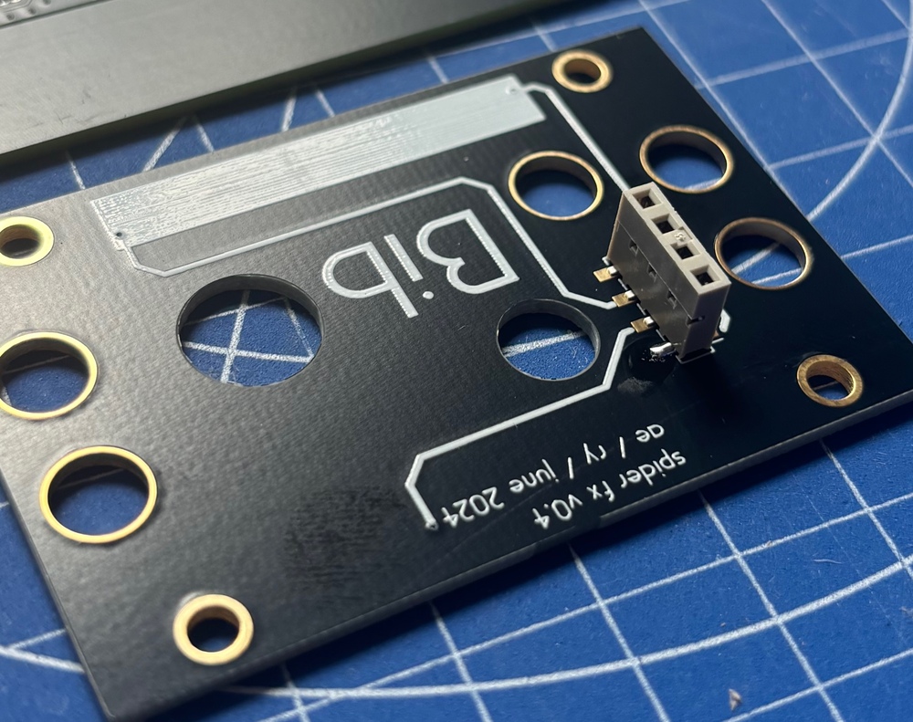
Let's get the two 'SMD' headers out of the way - the small 4 pin socket for the front panel which I missed out of the photo above, and a 2x3 pin header that you can use to connect line level stereo input and headphone output to the quarter inch TRS jacks on an intellijel palette case, for example.
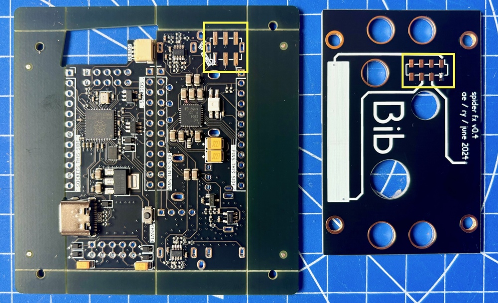
Your small socket should have 4 'holes' - but it may have 8 legs (like the one pictured), or 4 in an alternating pattern (2 on each side). Either works! The footprint has 8 pads to accomodate either type.
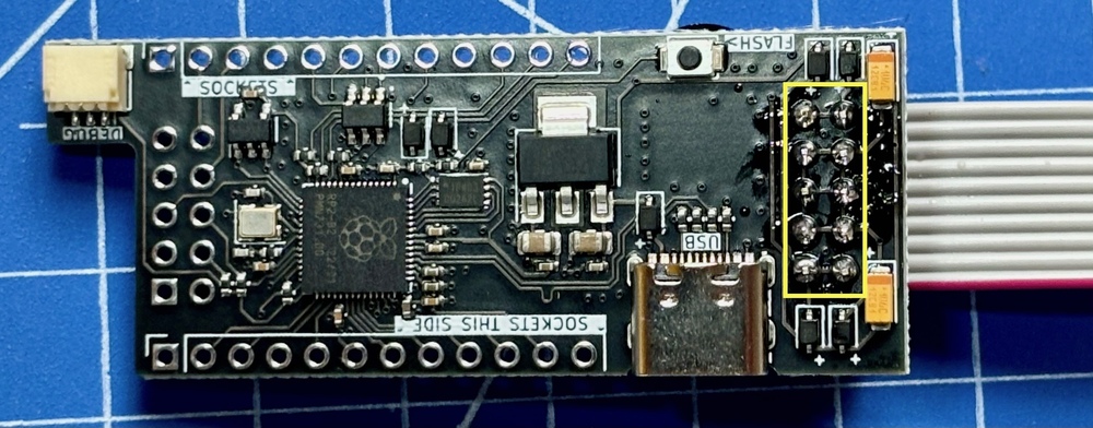
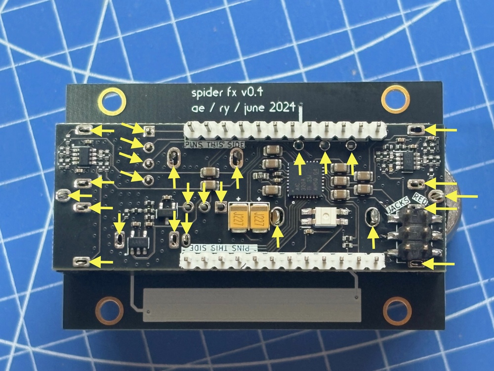
Put a small pillow of solder on a single pin on each footprint - one on the front panel, one on the main circuit board, as hilighted in yellow below. Again - just a single pin each for now!
now line up the socket and use your iron to heat up the pillow and solder that first pin. It's worth getting the socket nice and straight, centered, and upright while only 1 pin is soldered.
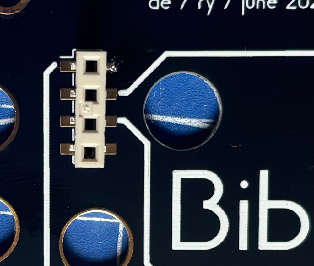
Don't bend it! just touch your iron to re-heat it and gently move the socket into place while the solder is melted. Once you're happy, it should look like this:
Now solder the remaining pins on the two connectors. Be careful on the mainboard not to disturb any of the tiny, pre-soldered components. The trick with soldering is to make sure your iron is warming both the pin to be soldered, and the pad it rests on. Heat them together for 1 or 2 seconds, then add a touch of solder. It should flow across both the pin and the pad, to make a nice soldered connection. Feel free to touch up the original 'anchor' pin on each connector.
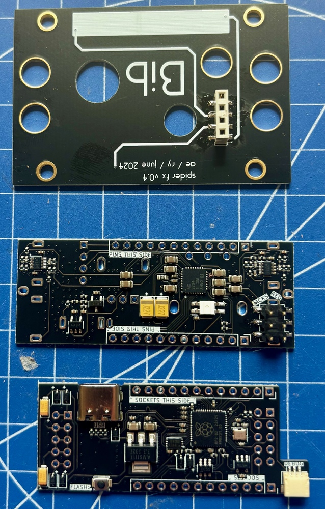
Lastly, gently break the spare 'rails' off the edges of the main board, using a pair of pliers and gentle pressure. When separating the two halves of the main board, I use my fingers and try to avoid 'flexing' either board - there are tiny hair thin metal traces inside the fiberglass, so you don't want to flex it too much. Once you're done, you should have 3 boards: the front panel with the 4 pin socket you just soldered, an analog board with the 6 pin header, and the digital board with the USB-C port on it. Lovely!
Preparing the pins
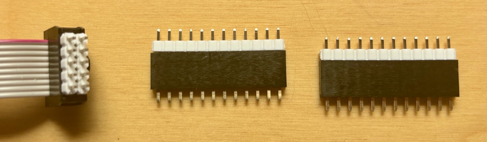
If your kit came with a 36 pin strip and a 5x2 pin 'block', then break the 36 pin strip into a section of 4, 12, 12 pins (and 8 spare). You'll use the 5x2 for the power.
If your kit came with a single strip of 40 breakable pins, break it apart now into 5, 5, 4, 12, 12 pin sections - you'll use the pair of 5s to make the power header:
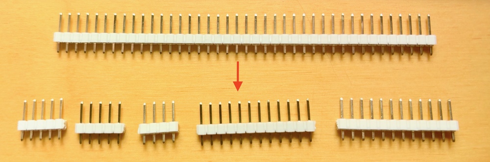
Connect the 12 pin pieces with the corresponding sockets, and push the 5 pin pieces into the eurorack power cable to line them up:
Soldering the eurorack power pins
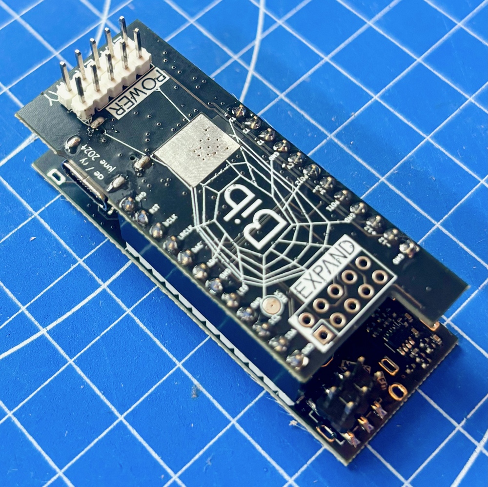
Now, with the cable still attached, put the 5x2 power pins into the back of the digital board, where it says 'POWER EITHER WAY'. You can ignore the 'expander' 5x2 holes, as the bib expander hasn't been designed yet. Better to leave it unpopulated for now, so you don't accidentally plug power into it in the future. :)
Turn it over, and solder the 10 power header pins. Again, be careful to avoid melting or disturbing the tiny pre-soldered parts, and be sure to heat both the pad and the pin before adding solder. These pins are actually the hardest to solder in the entire project, because they are connected to lots of copper inside the board, and will 'suck up' a lot of heat. Don't be afraid to really heat them up, to allow the solder to form a nice joint. Don't just add lots of solder! If you bridge some of the central 6 pins (ie the center 2x3) that's not the end of the world, as they are all 'ground' - but it's ugly! :) It will work though. The 2 pins on each end are +12 and -12, so you dont want to bridge them to the center, lest you short out your eurorack power supply. Take your time, it'll be ok!
Making the sandwich: 12 pin headers
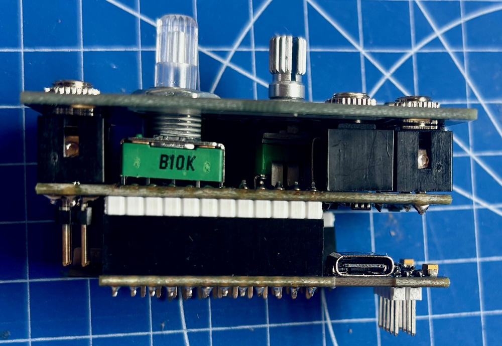
Ok now pop the 12 pin header+pin combos you made into both boards - we are joining them together in a kind of Bib-ish silicon sandwich. The pre-soldered components go on the inside of the sandwich, you see. Turn the board over to see the back with the Power pins you just soldered, and solder the two rows of 12 header pins, as shown below. I tend to solder a single pin first, and make sure it is all nice and square and flush, before soldering the rest. That's a good trick with multipin parts in general - do one pin, line it up, then do the rest when you're happy. It's much easier to align a single pin, than it is to fix things when you've soldered 12 wonky. Ask me how I know... Oh, while you're here, maybe melt a bit of solder into the USB-C connector's holes, if they are not already full. It just adds a bit of mechanical rigidity.
Solder the other half of the sandwich
OK! Flip Bib over and solder the header pins on the other side of the sandwich. You need to do this before putting the pots in, otherwise you won't be able to reach the pins!
Trimming the pot
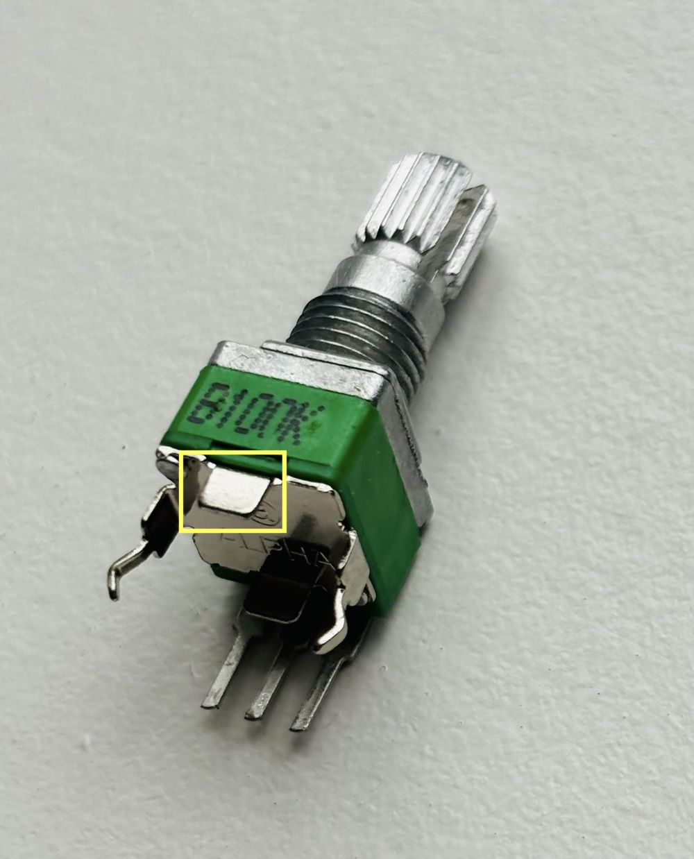
There's 1 tab you need to remove from the smaller pot. Use sharp side cutters, wear eye protection, avoid curious pets/kids, and get rid of the little metal tab shown in yellow below (on the small pot). You can also 'wiggle' it off with pliers - either way, make sure the whole vertical tab is gone, up to the base of the pot, otherwise it will short out some pins. While you're here, I tend to find the wiggly pins on the smaller pot a bit too wiggly for my taste - I flatten them very slightly with a gentle squeeze of some pliers. if you struggle to fit the pot into the board later, this'll help.
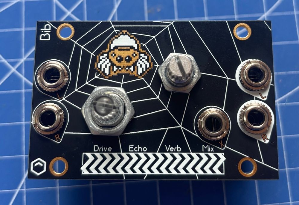
Placing the hardware (but not soldering it)
OK Now we're ready to put all the pots and sockets into Bib! prise the sandwich gently apart, if you didn't already, and put the digital half aside - it's finished actually! (Feel free to have a celebratory cup of tea). Freshly revitalised, remove the nut and washer from the smaller pot, but leave the silver nut on the larger pot!. I did not do this in the picture below, and I should have. You see, having that nut under the panel on the larger pot, helps to get all the heights equal underneath the panel. Anyway, place the pots along with the 5 Thonk jack sockets, and don't forget the little 4 pin header - as shown below. DONT SOLDER ANYTHING YET! Just plop 'em in place. The stereo pairs of thonkiconns actually share a single hole for the 'ground' pins, so it can be a bit fiddly, but you can do it! I believe in you!
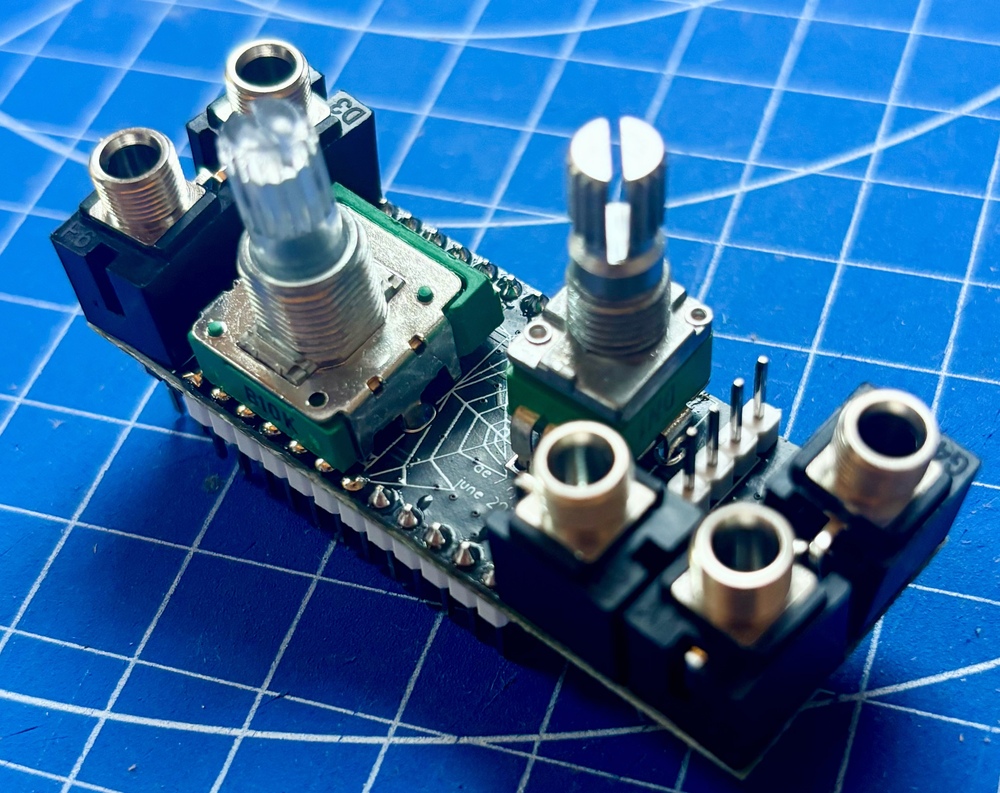
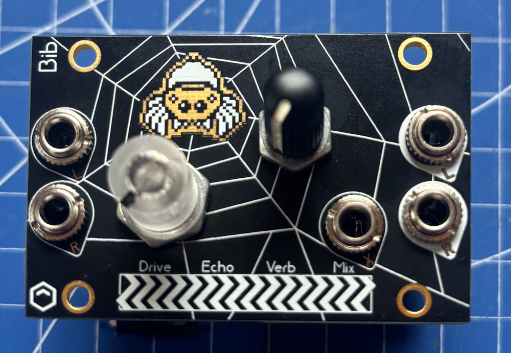
Why not solder them? You'll see! Now is the exciting moment we get to place the front panel over the top of everything. The pots and thonkis should all go through the holes (did you remember to remove the nut from the smaller pot, if one was there? good), perhaps after a little wiggling and persuasion (good thing you didn't solder them right!). The 4 pin header and the socket you soldered earlier should mesh together beautifully inside the sandwich.
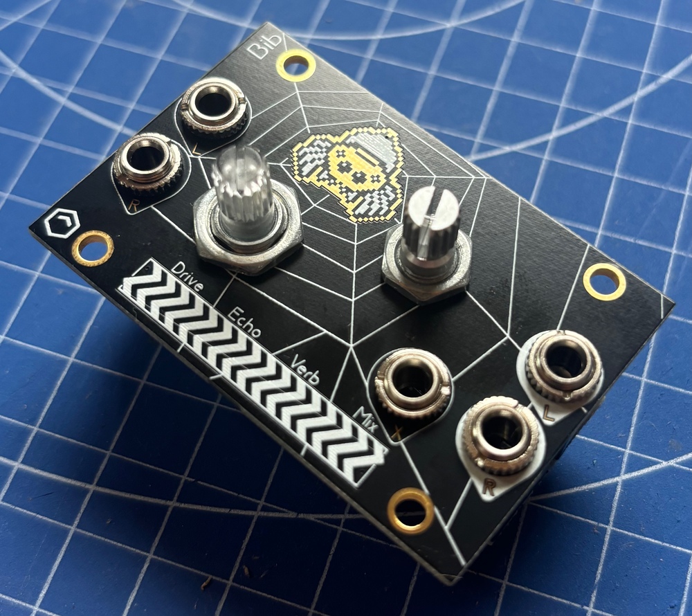
Take a moment to marvel at your achievement! I mean, why not loosely screw the nuts onto the pots and thonkis - it's really starting to look like a music thing now! Your kit probably included black nuts for the pots, and brass nuts for the thonkis which adds a certain je ne sais quoi... Alas, I didn't have those when I took the pictures below.
OK, NOW you can solder the hardware
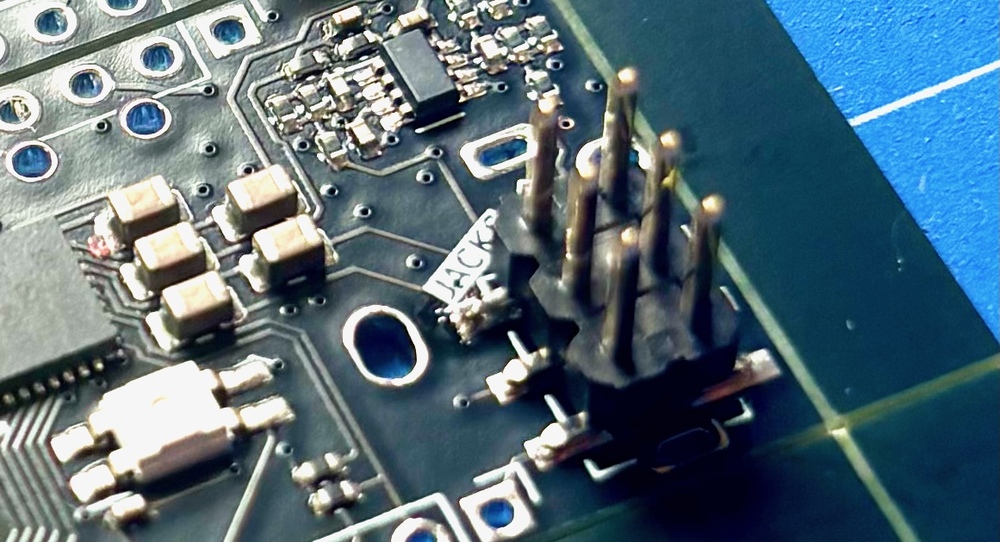
At this point you should solder all of the pins poking through the bottom of the board. Don't forget any! The 3 pins of the main knob, and the pins of the thonkiconn that straddle the 6 pin SMD header, are especially hidden. They're all marked with yellow arrows in this picture:
Hardware Victory
My goodness! That was it! Double check you got all the solder joints above - are you SURE you got the 3 next to the white pins, or the two either side of the 6 pin SMD pin header? SURE? SURE? OK! - then just plug the digital board back into your freshly soldered analog board, forming a 3 level club sandwich of Bibness. Make sure you get it the right way around - as shown in the picture. If things are a little wonky, that's ok - look at mine! Wonky, but it works. That's the Bib way. (You see, if I had left the nut on the larger pot, it wouldn't have been wonky! If only I had listened to Crazy Ray! Don't make my mistake - leave that nut on, and line that stuff up!)
All that remains is to tighten the nuts, push the knobs onto the pot shafts, and we'll install some software!
The Software Adventure
Your Bib kit should come pre-flashed with firmware, so in theory it should just work straight away without any further ado. If you want, go and read the manual.
However, if you wish to update Bib, read on.
First, download the firmware in this file: bib_007.uf2. Patch notes are available on the manual page.
Use a USB-C cable (not included) to plug your computer into Bib. You do not need Bib to be powered from eurorack for this step.
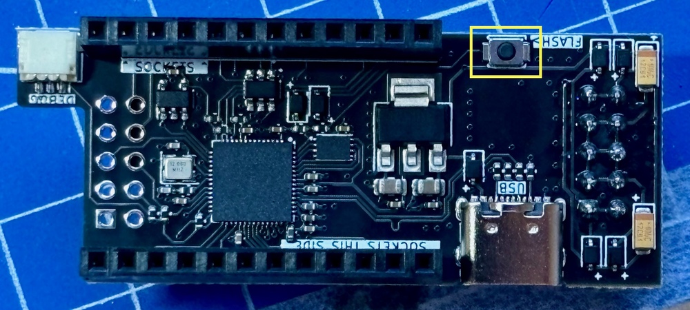
Bib should show up as a USB drive called RPI-RP2 (on mac, you may find it under /Volumes/RPI-RP2). If it does not, try disconnecting the USB cable, holding down the tiny button on the digital board, just opposite to the USB connector (hilighted below), while reconnecting the cable - then release the button. If it still doesn't show up, make sure your cable has data lines (and isn't just for charging). And if that's definitely ok - maybe check your soldering?
Assuming the drive shows up, drag and drop the bib_xxx.uf2 (where xxx is a version number) onto the drive. It should upload the software, and after a second, the main knob will flash white and then glow dimly (the colour will depend on what mode your Bib was last in). That's a good sign! that means your Bib is working!
Feel free to twist the knobs - the light should change brightness as you twist to reflect the position of the knob, and then revert to a dim glow when you release it. Pressing on the touch strip in each of the 4 zones marked Drive, Echo, Verb, Mix should cause the knob color to change Red/Green/Blue/White. If the touch is unresponsive, perhaps check your soldering - esepcially around the 4 pin socket and header on the front panel
Assuming all seems well, disconnect it from your PC, carefully connect it to your eurorack system (the power cable can be fitted either way), and - Happy bibbing!
If you want, go and read the manual.