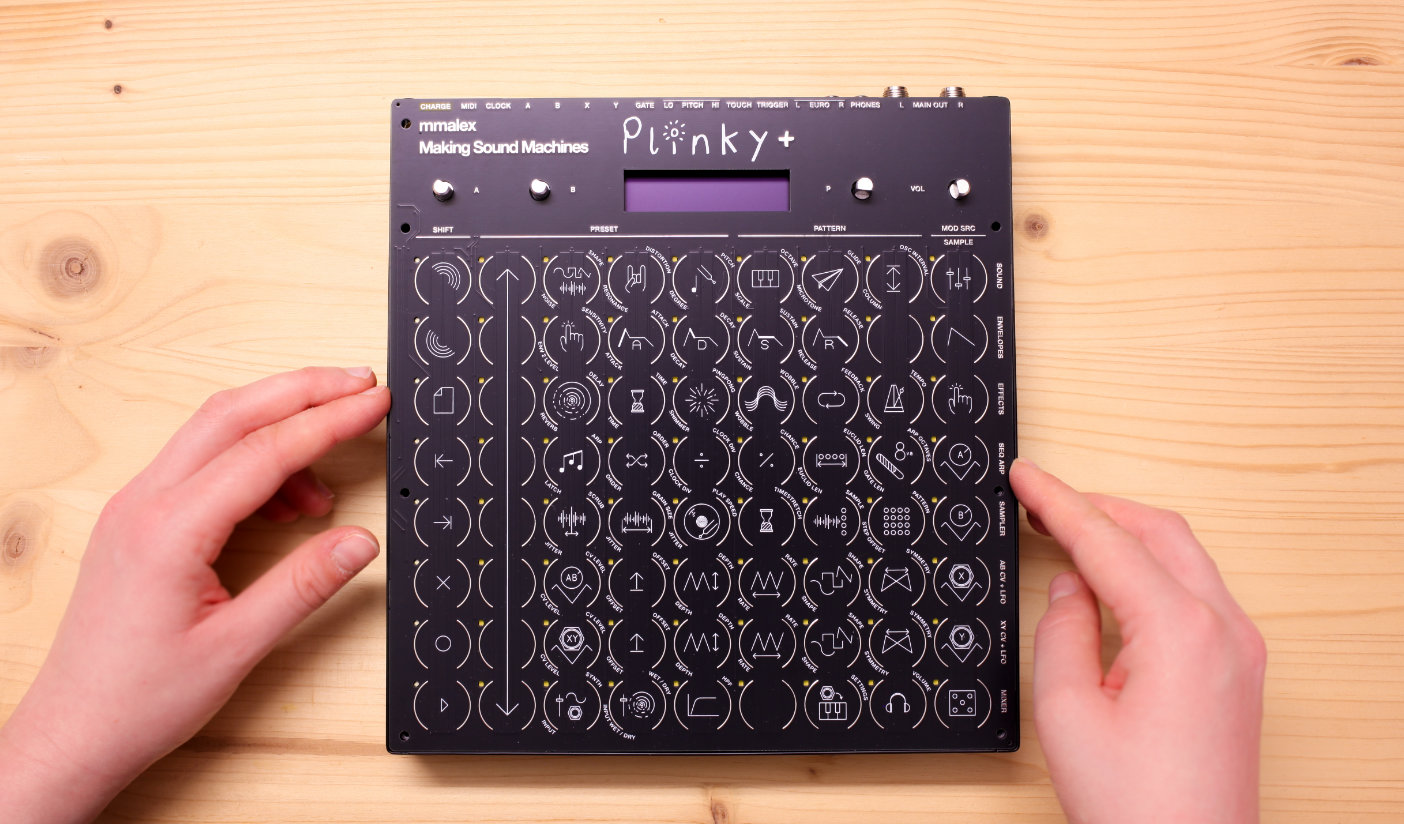
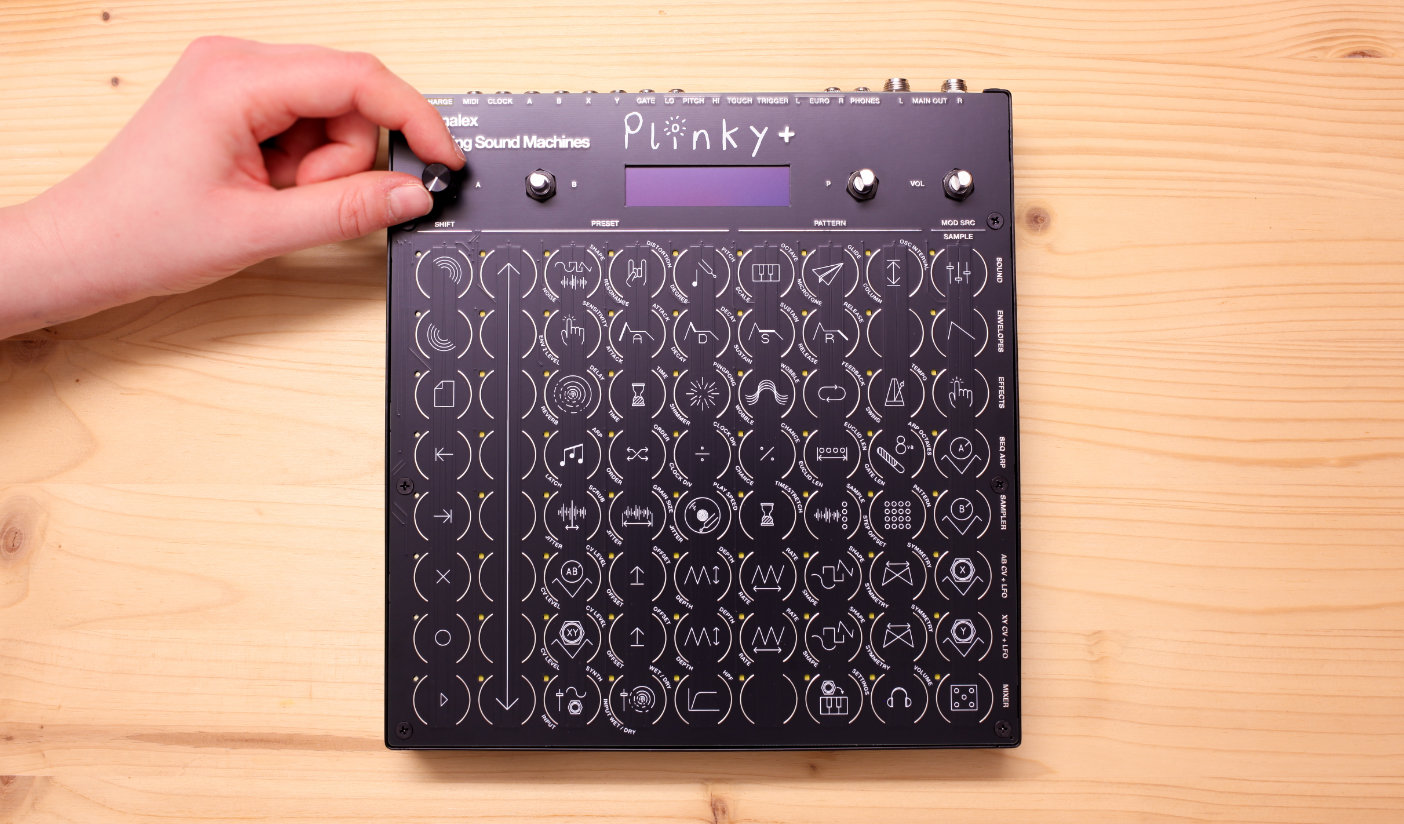
This is the build guide for the Plinky+ kit. It's easy to identify:
- it's larger than original Plinky - 21 x 22 cm (8.23 x 8.66 inches)
- four knobs at the top - it has an extra potentiometer for volume
- all inputs and outputs are on the back panel
- powder-coated metal enclosure
Check out the other build guide if you are building the original 24HP Plinky.
Build Video
Nathan Plante has made a fantastic video building Plinky+. Thank you for the wonderful video!
Nathan makes fantastic music with Plinky on his channel, it's absolutely worth checking out his complete Plinky Playlist.
Getting ready
Thank you for getting a Plinky+ DIY Kit.
Plinky+ is an easy mechanical build. No soldering is required - all PCBs come pre-soldered.
Some tools you will need
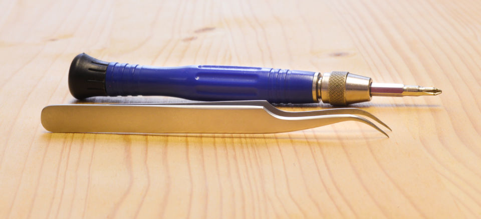
- A Phillips screwdriver
- Tweezers
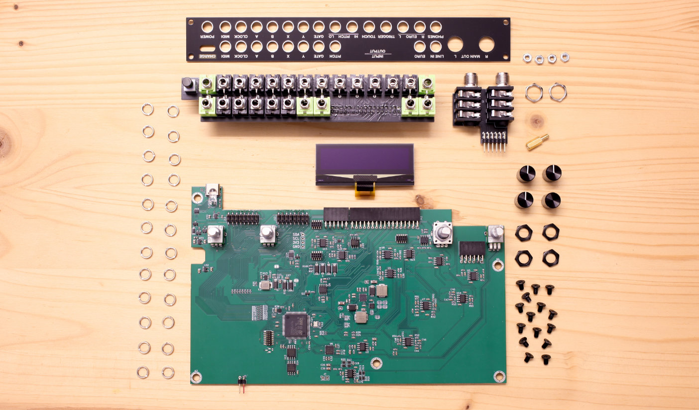
Here’s what you will find in the kit
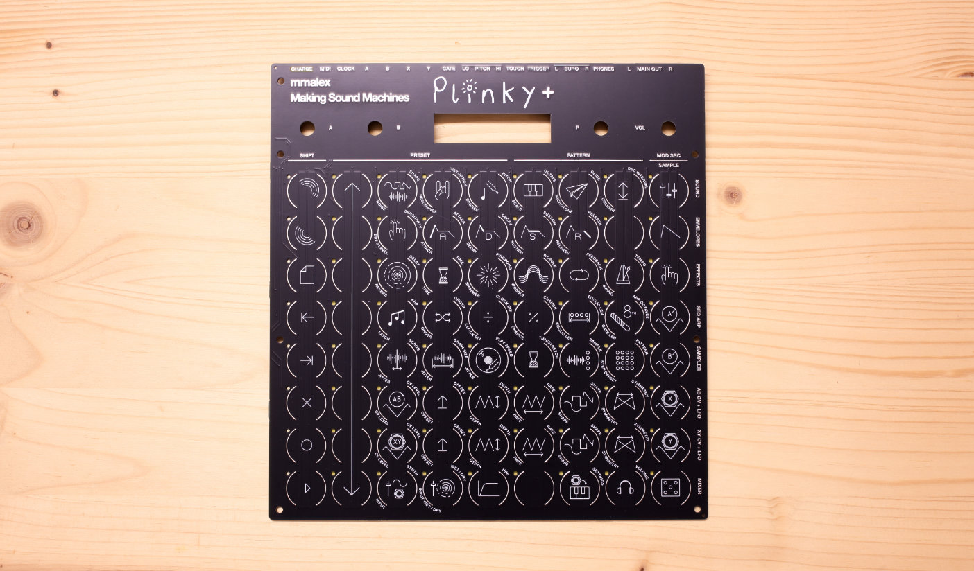
- The front panel
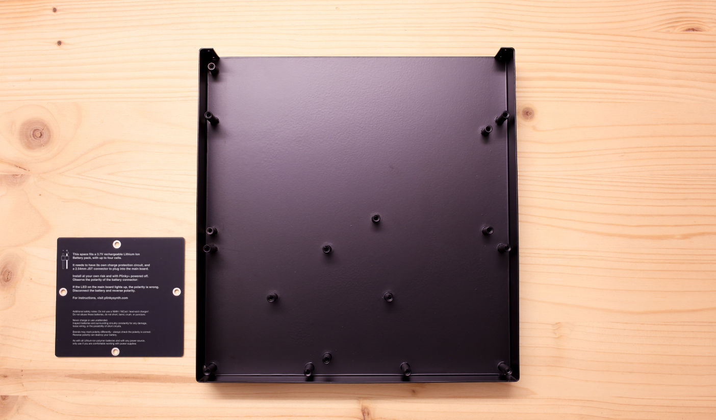
- The metal enclosure
- Battery cover
- 24x knurled nuts
- Back panel
- 3.5 mm jack board
- 6.35 mm jack board
- OLED screen board
- Mainboard with presoldered components
- 4x M3 nuts
- 2x 6.35 mm nuts
- 1x 10mm hex spacer
- M3 washer
- 3x knob caps with indicator
- 1x encoder cap without indicator
- 4x black hex nuts
- 21x black M3 screws
- 4x rubber feet
- Acrylic Lid
- Printed Manual
Build Guide
All of the soldered components on the PCB have already been assembled for you, so this is a very quick build. However, it does require careful handling of the PCBs and components.
Avoid touching the SMD components with your hands and be careful not to bend or stress the boards. Take your time, and do not overtighten screws.
Attach the back panel
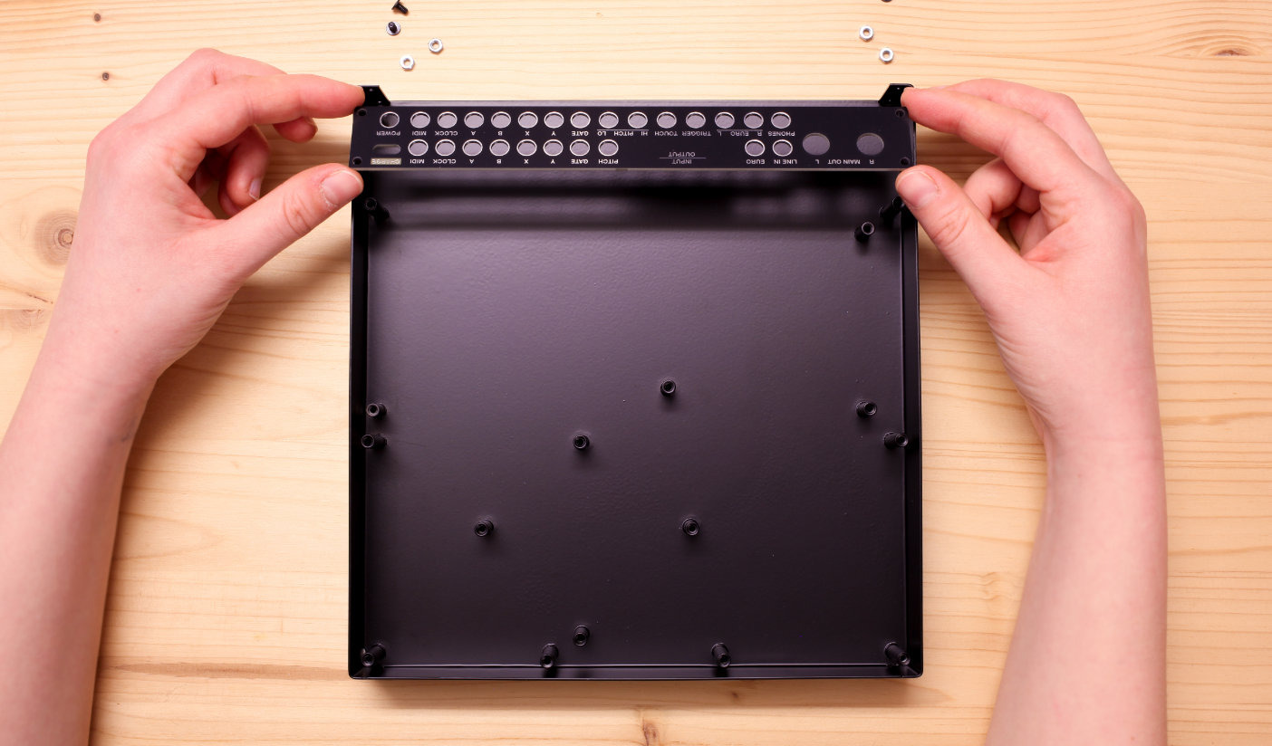
The first step is to attach the back panel to the metal enclosure.
The back panel sits inside the case. Four short M3 screws are inserted from the outside and held with four silver hex nuts on the inside.
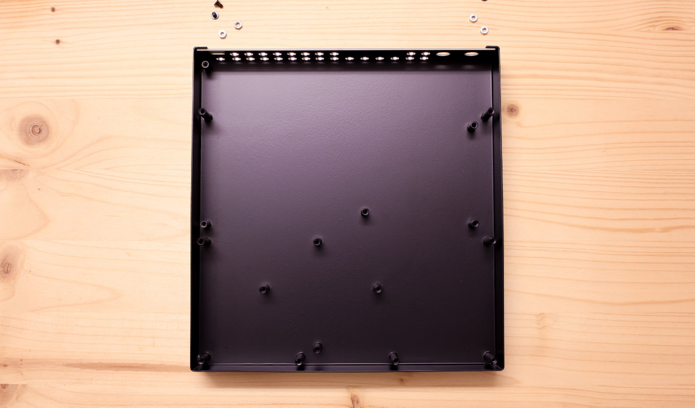
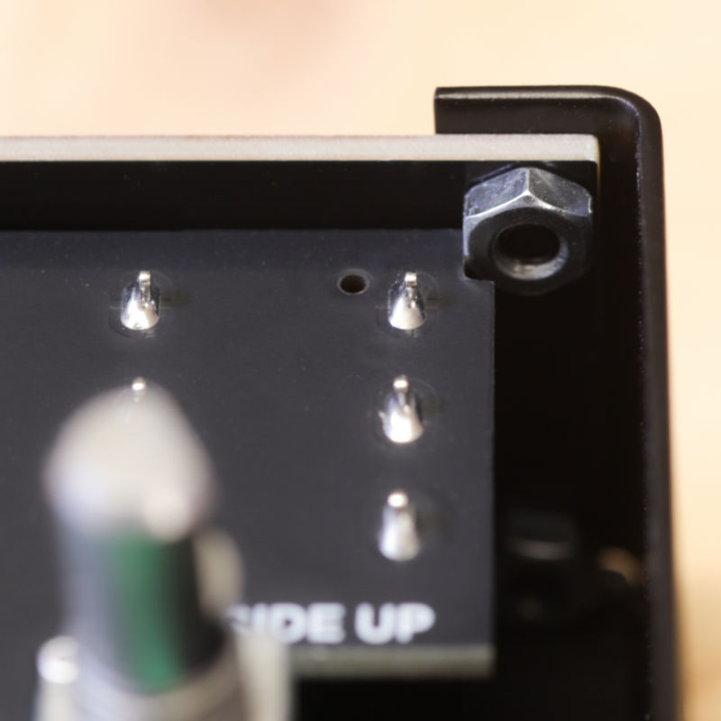
Slide the back panel into the case. Mind the orientation of the board: the silver labels above the jack cutouts face outside. The slot for the USB-C connector sits on the left, with the big cutouts for the Main Out on the right. Any printed labels are right side up.
Take a silver nut and hold it against the inside of the panel. Use your finger or tweezers to align the nut and hold it in place.
Using an M3 Phillips screwdriver, screw in each one of the black screws from the outside. Make sure to screw it all the way in, but don't over-tighten.
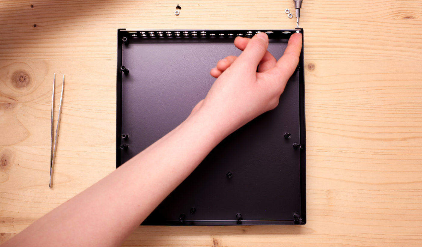
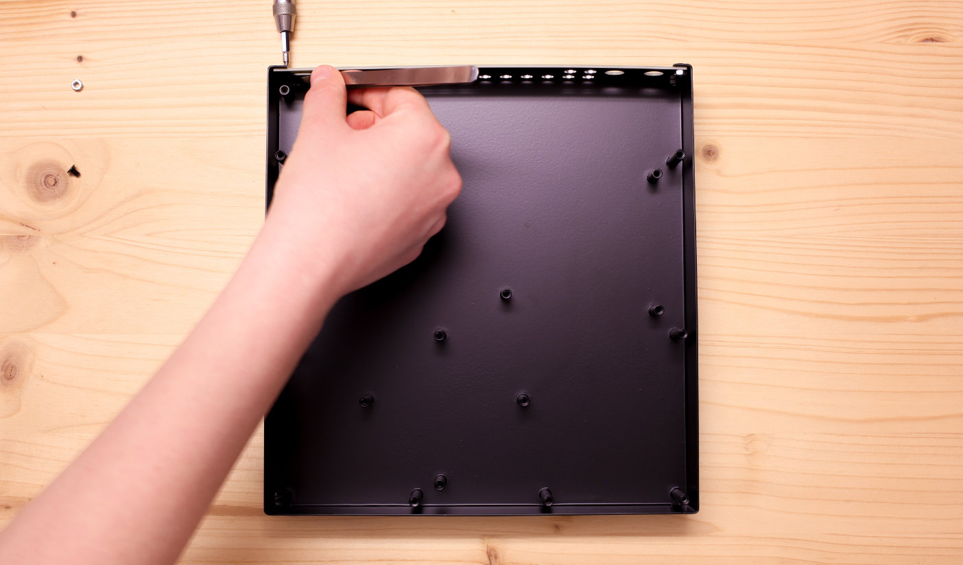
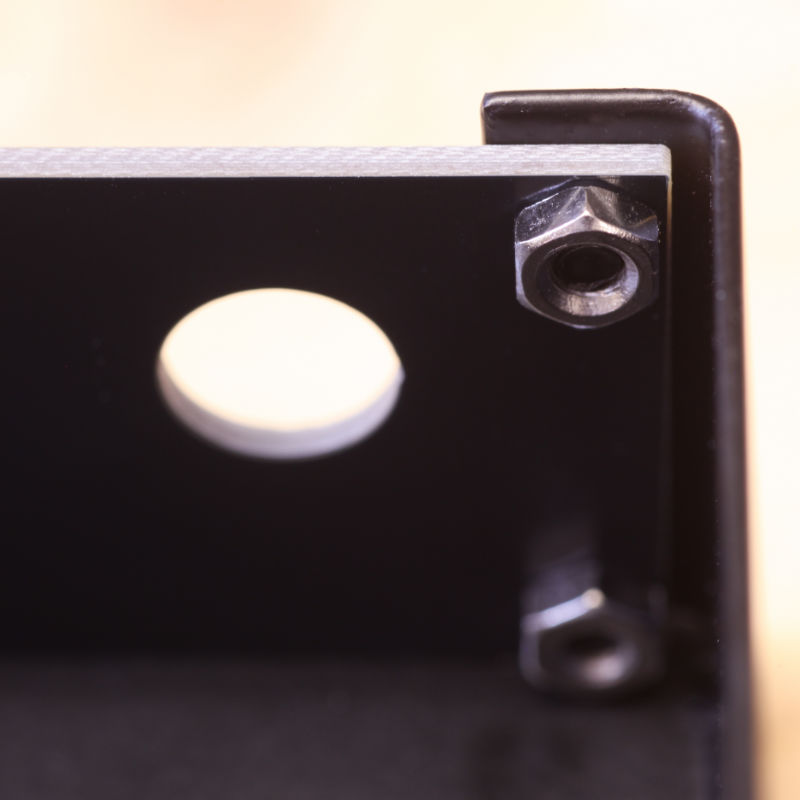
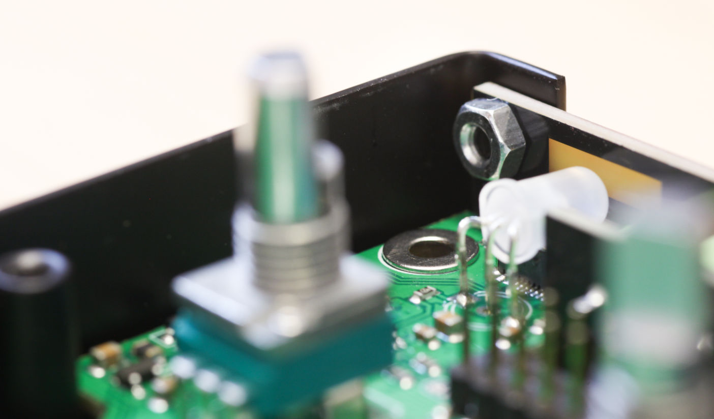
When screwing the silver hex nut in the upper right corner, please take care to align it so the pointy end of the hexagon points upwards. The 6.35 mm jack board has a small cutout that allows it to fit snugly against the nut. The simplest way to accomplish this is to not over-tighten screw and nut, and rotate the screw with the screwdriver so the hex nut faces the right way.
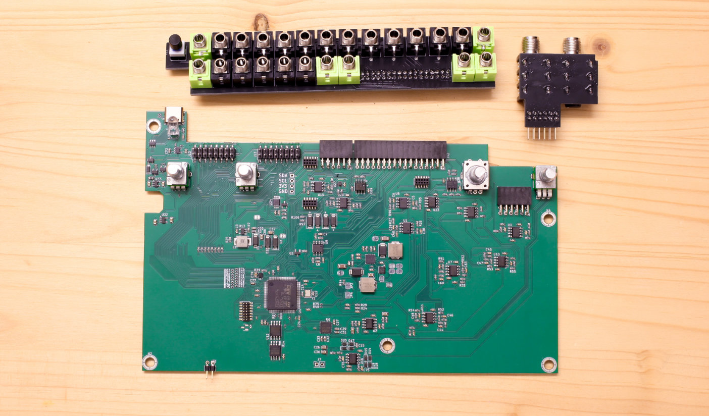
Assemble Mainboard and Jacks
For this step you need the mainboard, and both the 3.5 mm and 6.35 mm jack boards.
Place the mainboard in front of you, so that the component side faces up and the potentiometers sit at the top. Any printed labels are right side up.
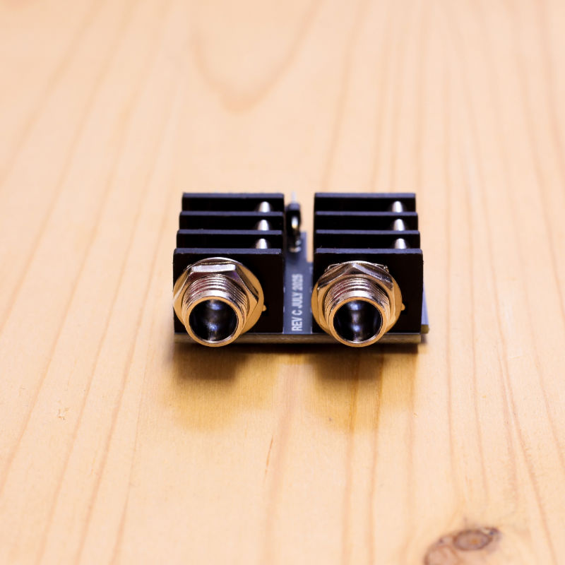
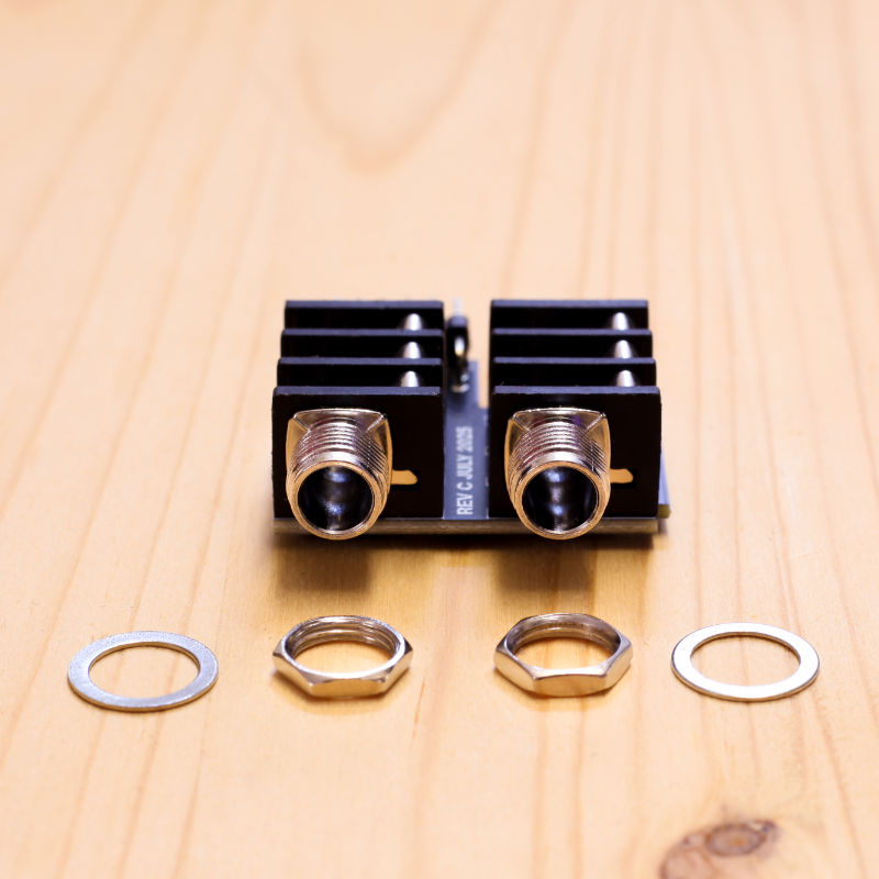
In your kit, you will find the hex nuts for the 6.35 mm jack board screwed onto the jacks. Unscrew the jacks and remove the washers, and keep them for attaching the jacks to the back panel later.
The smaller of the two jack boards, the 6.35 mm jack board with the big jack connectors, attaches to the pin socket on the right side of the mainboard. Note that on this board, the PCB sits on top of the jacks.
The 2x6 pinheader on the jack board slots into the 2x6 socket between encoder and stereo potentiometer. Line up the header with the socket and push the board in.
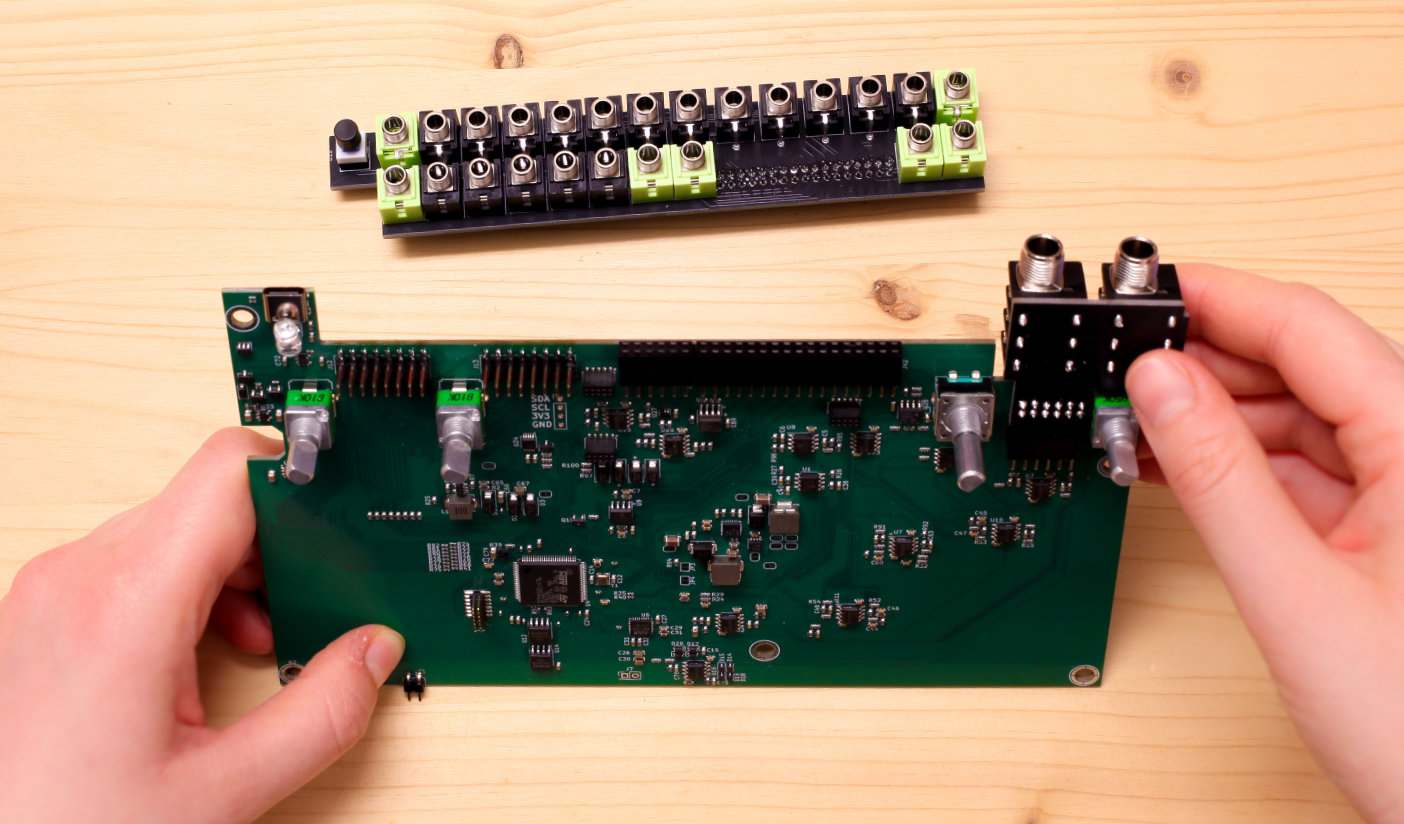
Next, place the 3.5 mm jack board, the longer of the two boards with two rows of jacks. The on/off button faces to the left, and sits under the USB connector on the mainboard.
The 2x27 pinheader on the jack board slots into the 2x27 socket on the mainboard. Note there's a second, separate socket that remains unconnected.
The pins align with the socket on the right side. Line up the header with the socket and push the board in.
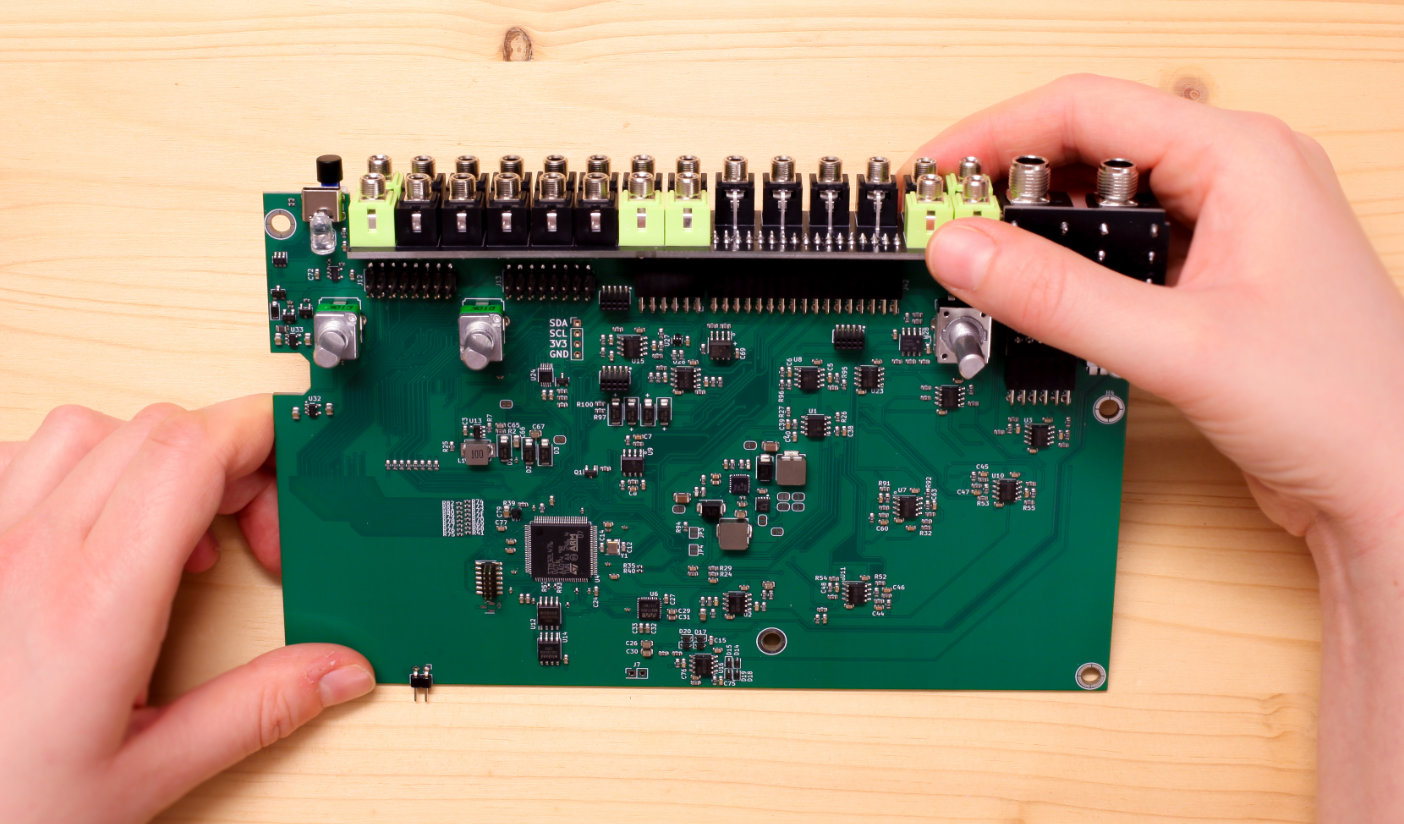
Once you have connected both the smaller 6.35 mm and the longer 3.5 mm jack board to the mainboard, you are ready for the next step.
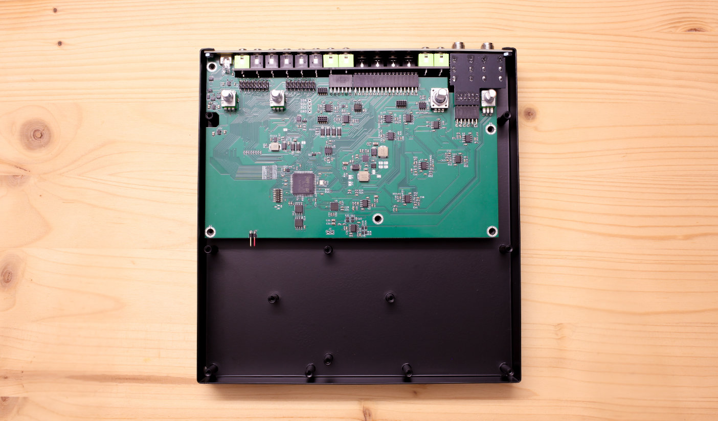
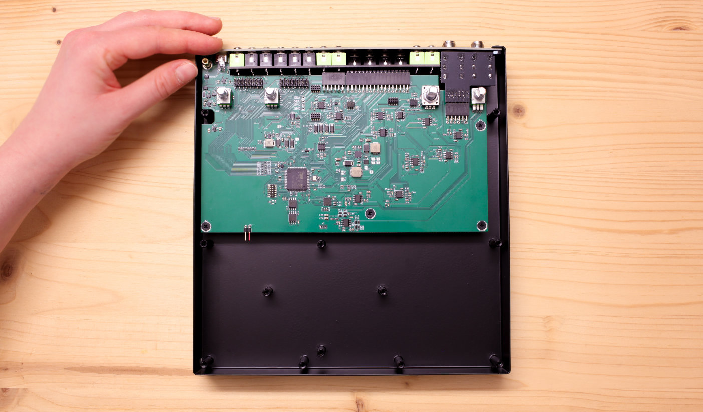
Place mainboard in metal enclosure
The mainboard, with 6.35 mm and 3.5 mm jack board connected, needs to slot though the back panel so it sits in the metal enclosure.
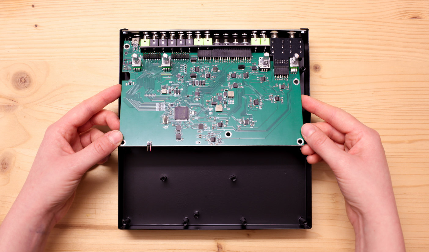
The best way to do this is to hold the mainboard at an angle, and align the jacks with the top row of cutouts of the back panel.
Use the jacks and cutouts as a pivot point, and lower the back of the main board so the jacks slide through the panel.
Gently push the board forward. It may be necessary to give the board a little wiggle, so all parts fit through the holes.
If done correctly, all jacks slot through their corresponding cutout in the back panel. The mainboard sits on the standoffs so its 5 screw cutouts align with the standoffs themselves.
Now you are ready to screw the mainboard into the metal enclosure.
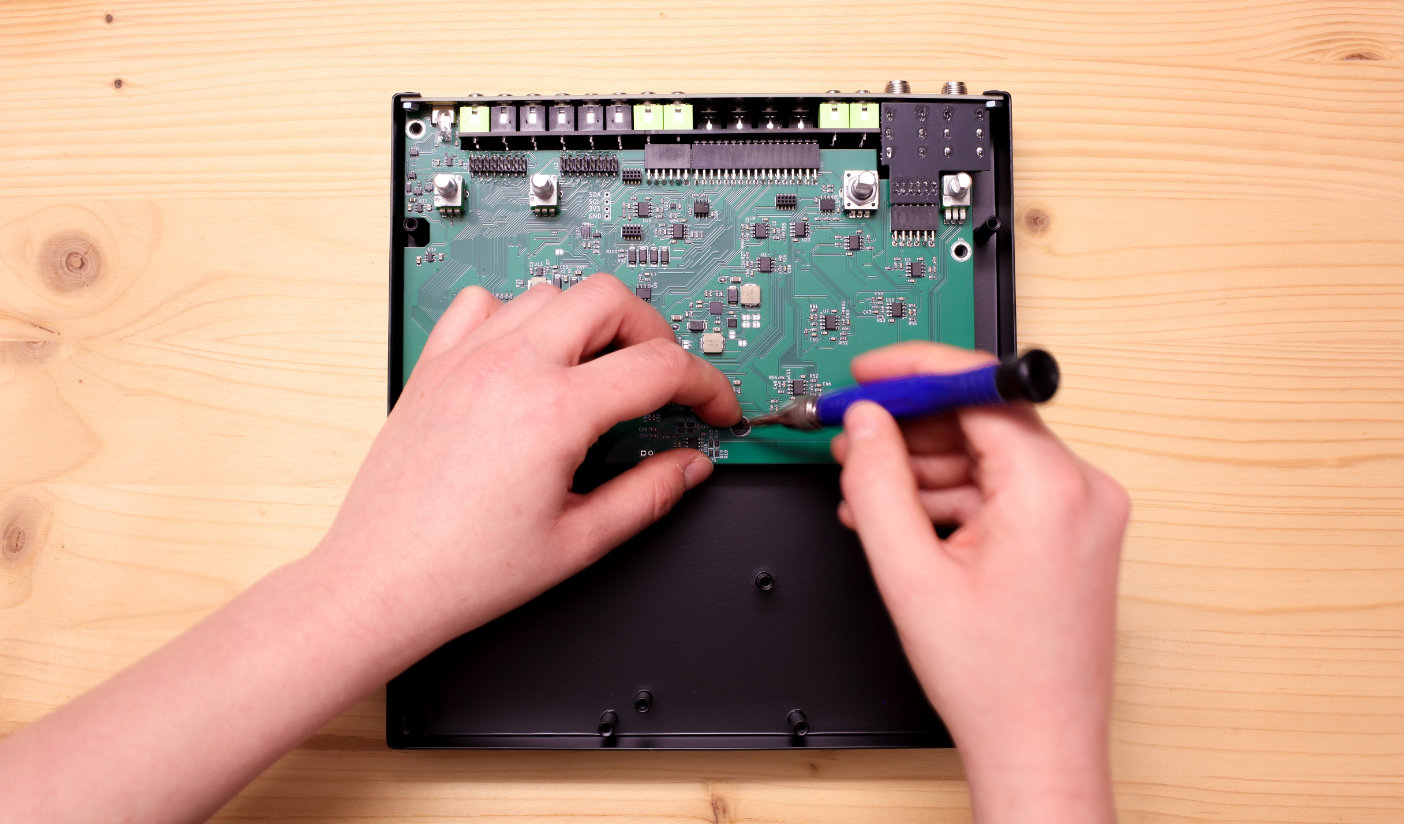
Take 4 of the black M3 screws. They go into the 3 positions on the bottom of the mainboard, and the one on the right side, under the volume potentiometer.
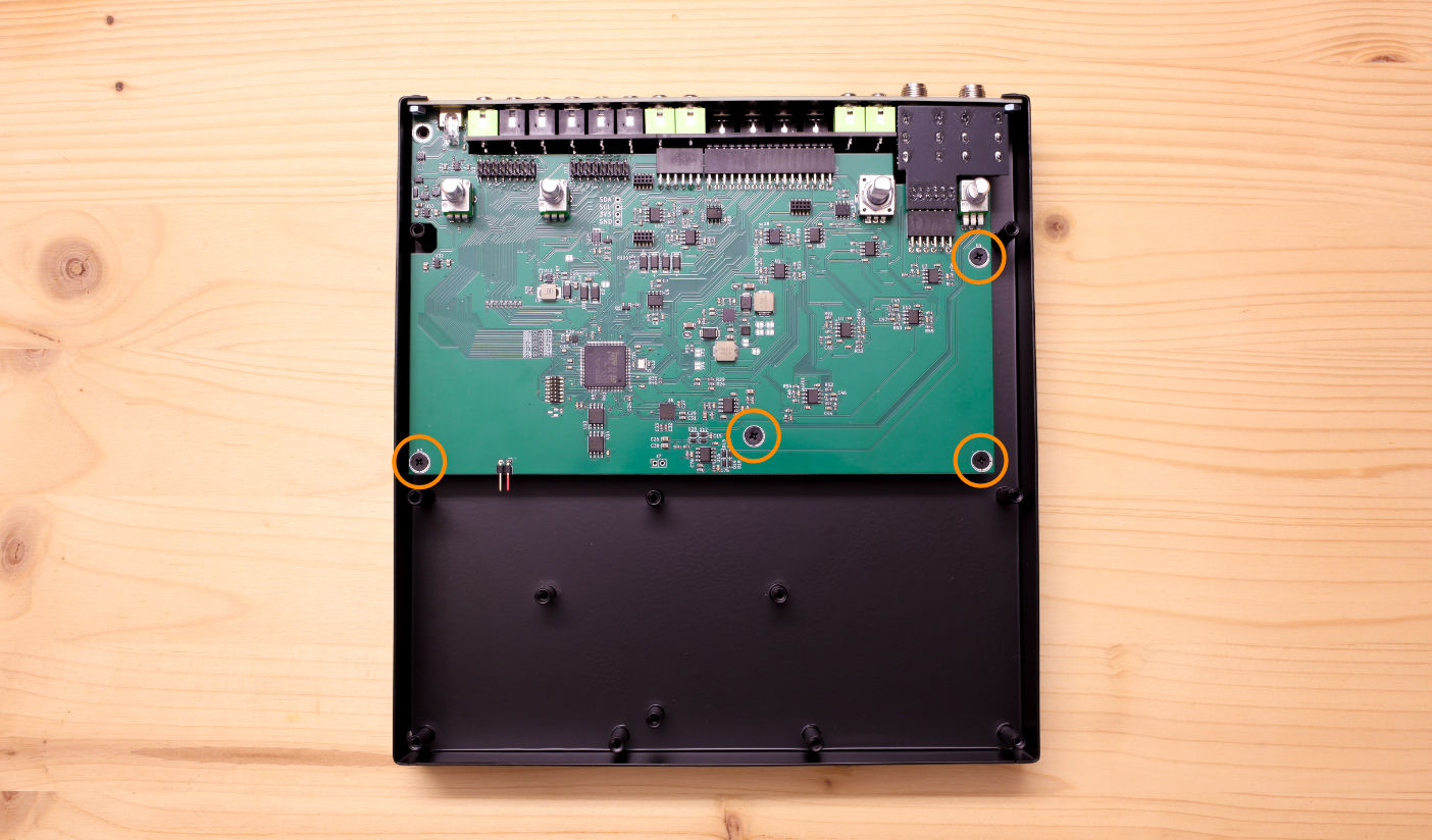
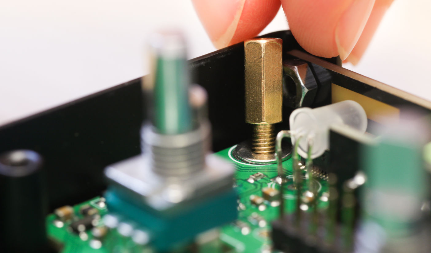
The golden 10mm hex standoff goes into the position at the very top left, next to the USB-C jack, with the M3 silver washer between the standoff and the PCB.
It's easiest to first place the M3 washer on the PCB, then screw in the gold metal spacer.
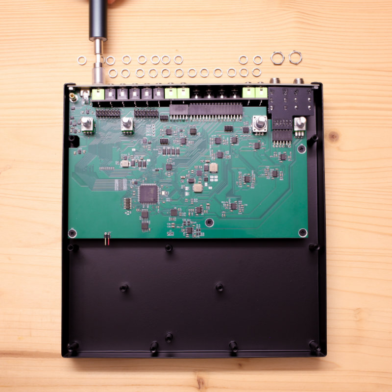
Place the knurled nuts
Once the mainboard is securely attached to the metal case, you need to place the knurled nuts to attach the jacks with the back panel.
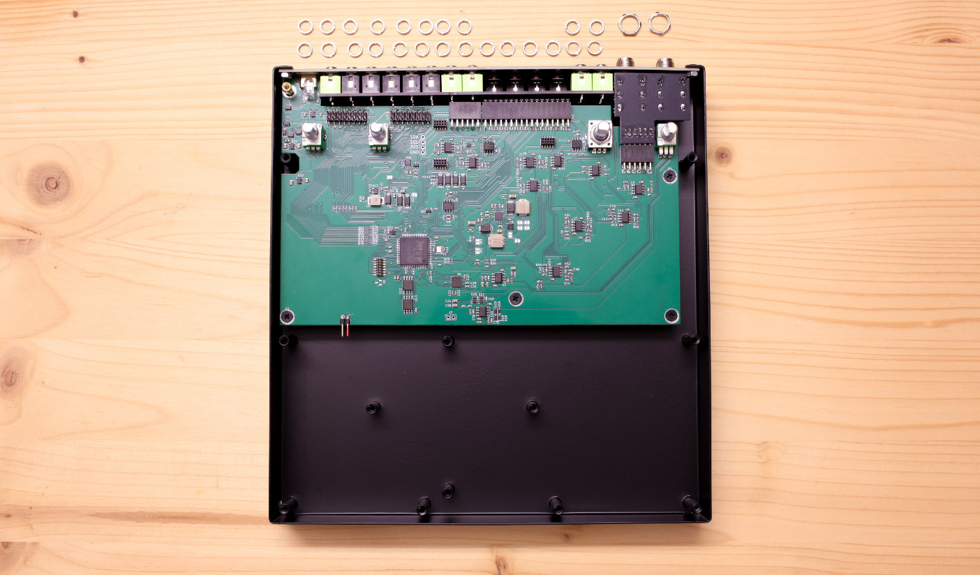
Find the 24 knurled nuts. These go on the Thonkiconn jacks
Then find the two largest silver hex nuts. These go on the two 6.35 mm Main Out jacks.
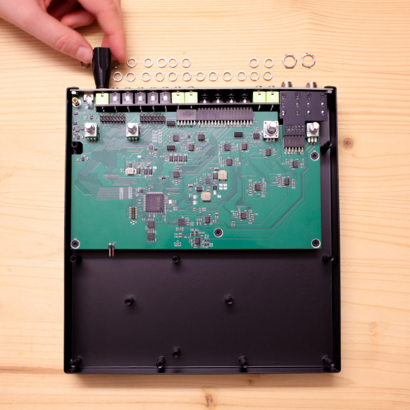
You can either use your fingers or a tool to tighten all 26 nuts. You can find tools for knurled nuts at Michigan Synthworks and Exploding Shed, but if you are just doing these 26 here, doing them by hand will be fine. If you use a tool, be careful not to scratch the back panel.
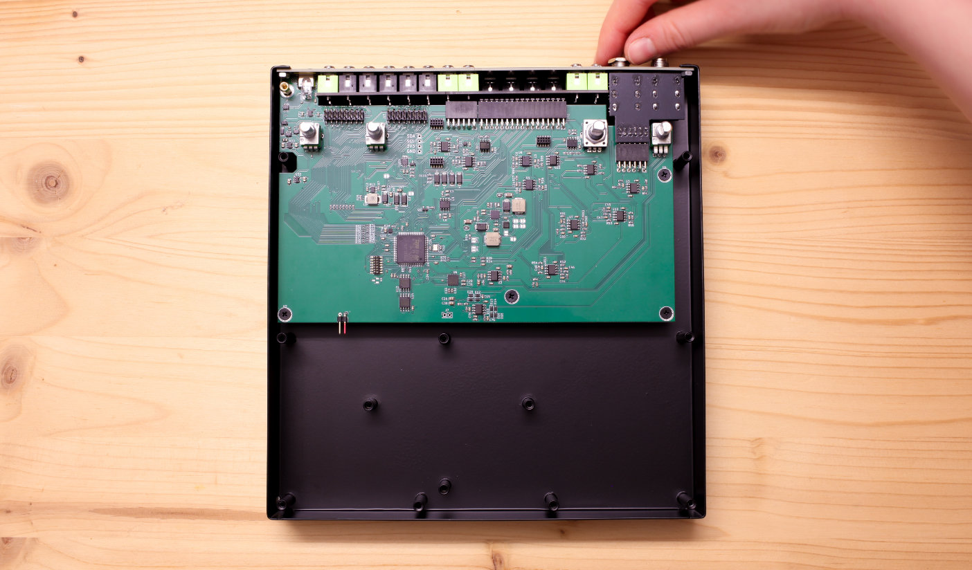
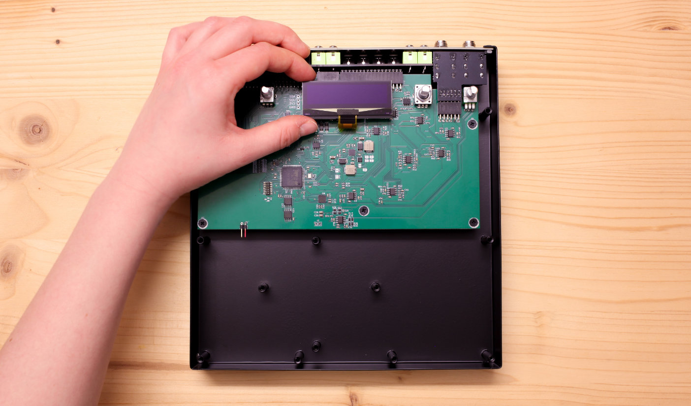
Place the OLED board
The OLED screen comes tested and pre-assembled on the OLED board. All you need to do is to fit it into the 3 small headers on the mainboard.
Make sure the 3 pinheaders on the OLED Board align exactly with the sockets on the mainboard, then gently push the OLED board down into the sockets.
First power up
Before placing the front panel, do a quick first power-up.
Attach a USB-C cable to Plinky+. We recommend using a simple USB phone charger with around 1A power and a USB C to A cable.
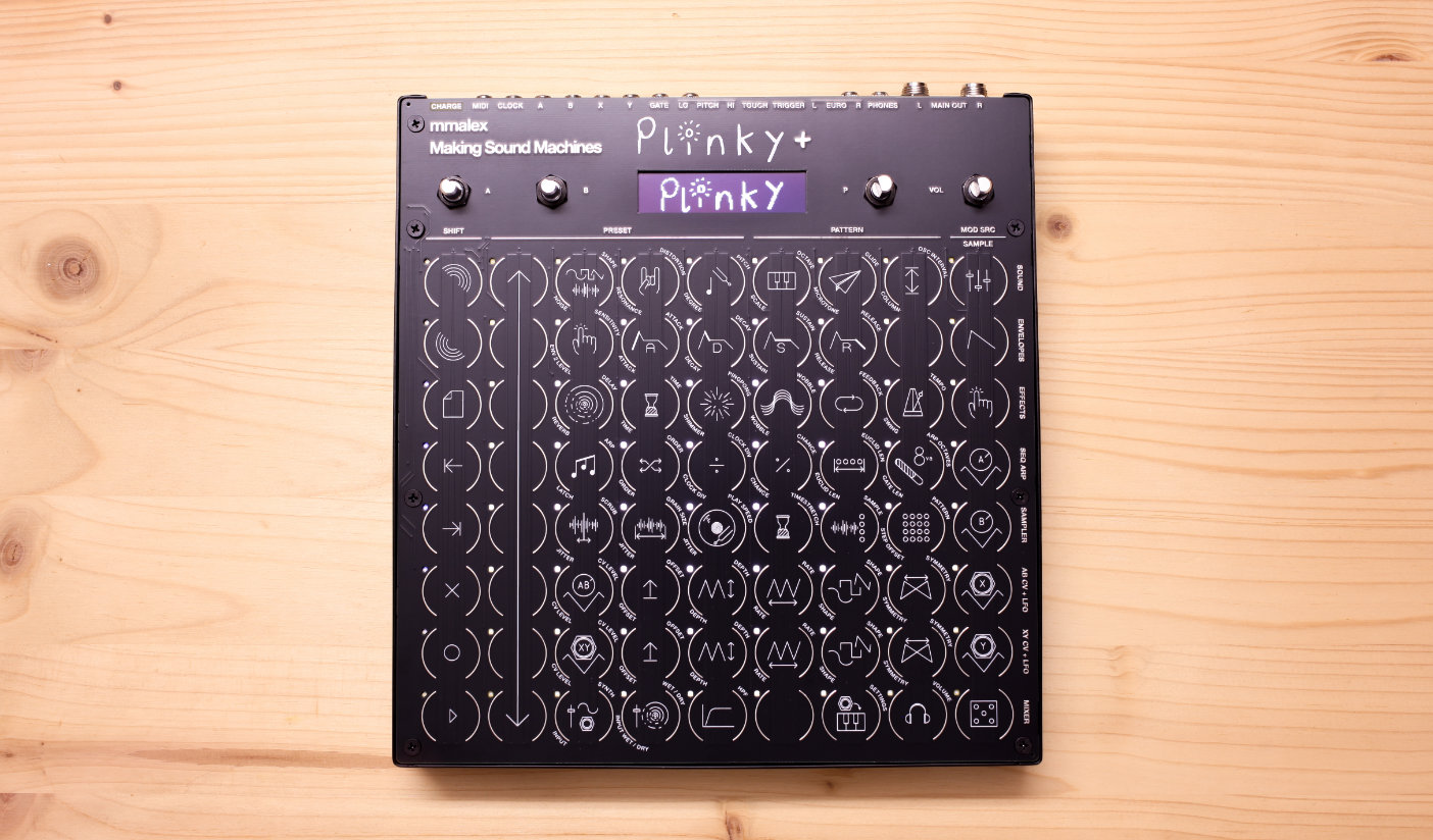
Then push the power button. Plinky+ will boot up and show the calibration menu.
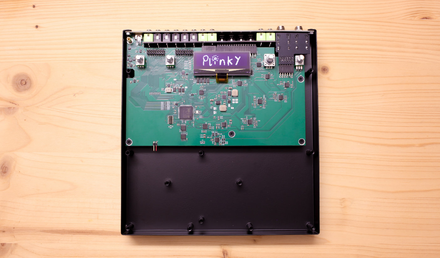
Now that you confirmed the OLED screen is assembled correctly, you can move on to finish the build. Press the on/off button again to power Plinky+ off and remove the USB cable.
Now is also the best time to remove the anti-scratch cover from the OLED screen. It's a little translucent adhesive with a green plastic strip you can just lift off the screen.
If you intend to install a built-in Battery Pack, and you have already sourced one, you may want to jump to that chapter and return here afterwards. Note that installing a Battery Pack is at your own risk. A suitable Battery Pack needs to be purchased separately through a third-party vendor.
Place the Front Panel
Take the Front Panel, printed side up. It needs to align with and slot over the potentiometer and encoder.
The front panel has two grey 2x8 sockets on its underside, which line up exactly with the two 2x8 pin headers on the main board.
Align the sockets and headers so that they match, and push the front panel down.
Make sure that it is sitting flush and aligns with the metal case. You might need to carefully push it down around the sides to completely sit inside the case.
Check one last time that you removed the anti scratch cover from the OLED screen.
Screw down the front panel
The cutouts in the front panel should align with the welded studs underneath. Use the remaining 9 black M3 screws and screw the front panel to the metal case.
Now with the 4 black hex nuts, secure the 3 potentiometers and the encoder to the front panel. Don't overtighten the screws and the nuts, anything you can comfortably do by hand is perfect.
Congratulations, your build is done!
The hardware part is done. Take a moment to appreciate the majesty of your crafting skills.
Now is a good time to stick the 4 included rubber feet to the back plate. It's not strictly necessary to keep Plinky+ from moving around when sitting on a table top, but a good option if you are worried about scratching the surfaces Plinky+ sits on.
They are self-adhesive. Peel them off the wax paper and place the rubber feet in all four corners of the back of the metal enclosure.
Only once you’ve tested the functionality of your Plinky+, put on the aluminium knob caps.
Power up your Plinky+ and Calibration
Connect Plinky+ to a power source (PC or Mac USB port, or USB power adapter) and push the on/off button to power it on.
Plinky will go into touch calibration mode the first time it boots. Calibration mode is indicated on the display, and the bottom row of LEDs light up. You can watch the calibration process in this video.
Touch calibration
In calibration mode, one LED in each column will be lit. Press your finger evenly and as centrally as possible on one of the lit pads, medium hard (mezzo-forte) for a few seconds. After a few seconds, the LED will start blinking and you can release the pad.
Plinky will ask you to do this for all 72 pads, by lighting them in turn.
If you aren’t quite central with your finger, don’t release - just slide your finger into place with it held down, and keep it held down a few seconds once it’s central. If you completely mess up, switch Plinky off and on again, and try again.
Once you’ve finished, your Plinky is ready to play!
You may need to recalibrate Plinky
- if it is responding offset to your finger presses
- if you buy a previously owned Plinky
Twist the leftmost knob as Plinky powers up, then follow the steps described above.
Put on the Knob Caps
Plug in headphones or speakers, play the touch surface with your fingertips and check whether you can hear audio. Use the righthand knob to carefully adjust the volume, start with a low setting first.
Do a little test-drive. If everything is working fine, put on the knob caps. The caps have a profile for a D-shaft inside, so they are keyed to align correctly with the potentiometers and encoder.
Potentiometers A, B and VOL each get a knob cap with a white indicator line, the Encoder P gets one without marking. If the knob is correctly aligned with the D-shaft, you can simply push it on.
Happy Plinking
Congratulations, the build is done! Happy Plinking!
Please check out the Play Guide and the Manual.
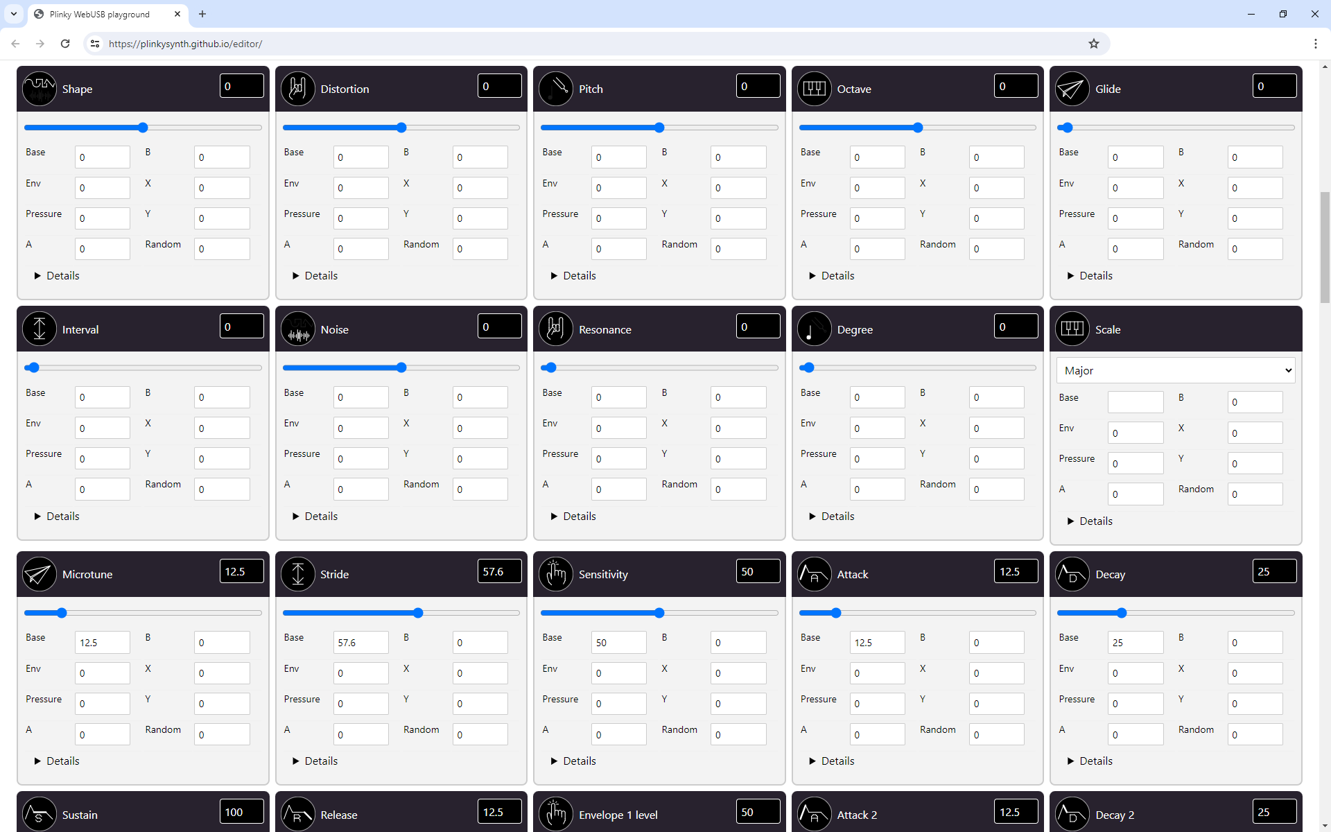
Plinky also has a browser-based patch editor at plinkysynth.github.io/editor. You will need a Web-Serial enabled browser like Google Chrome to run it, and allow it to connect with Plinky. On Linux, you will need to grant hardware access to Plinky.
Installing a Battery Pack
While Plinky+ does not come with a built-in battery, it has the circuitry and a connector that lets you retrofit a battery pack.
You are retrofitting a Lithium-Ion Battery Pack at your own risk. As with all Lithium-ion polymer batteries, only proceed if you are comfortable and experienced working with power supplies.
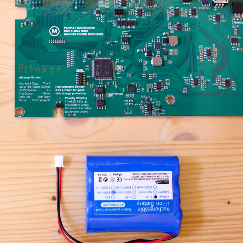
Plinky+ can be powered from a 3.7V rechargeable Lithium Ion Battery Pack, with up to four 18650 cells. The Battery Pack needs to come with its own charge protection circuit, and a 2.54mm JST connector to plug into the main board.
Battery Packs
Here is a list of Battery Packs we tested with Plinky+.
3.7V Rechargeable Lithium Battery Pack 18650
MLMTEY Store - Aliexpress
9000mAh (3 cells) or 12000mAh (4 cells)
Polarity: Black - / Red +
Needs adapter: No
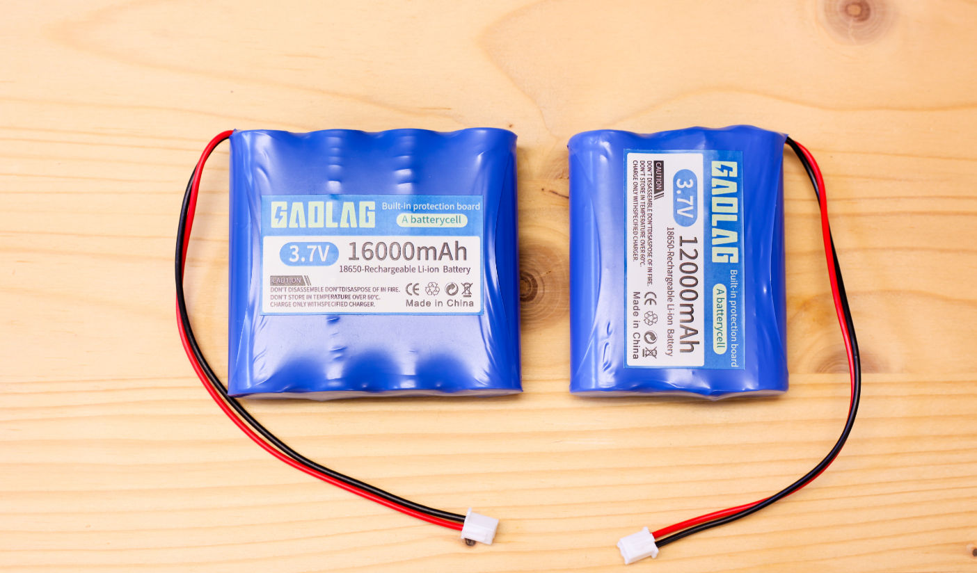
Lithium Battery 3.7V 18650 with XH2.54-2P Plug
GM Battery Store - Aliexpress
12000mAh (3 cells) or 16000mAh (4 cells)
Polarity: Black - / Red +
Needs adapter: No
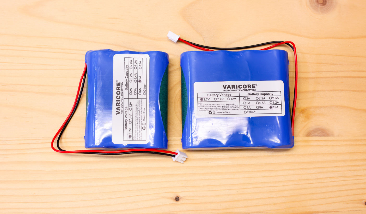
3.7V 18650 Lithium Battery Pack
VariCore Official Store - Aliexpress
1S3P 9000mAh (3 cells) or 1S4P 12000mAh (4 cells)
Polarity: Black - / Red +
Needs adapter: No
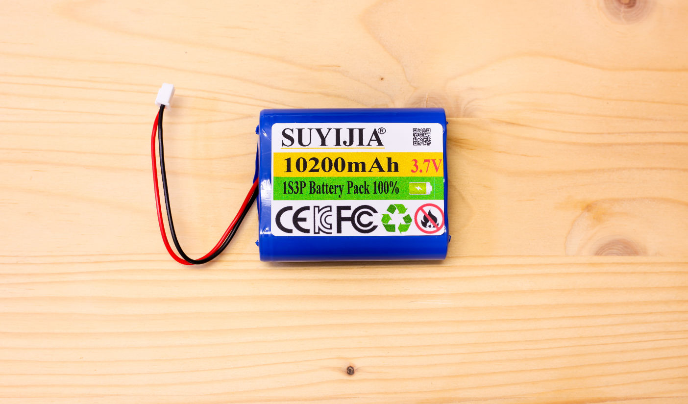
18650 3.7V 10200mAh 1S3P Battery Pack Lithium-ion
SUYIJIA AAA Battery Store - Aliexpress
1PCS 2P plug (3 cells)
Polarity: Black - / Red +
Needs adapter: No
Battery Installation Video
Nathan Plante has made an additional video that shows him retrofitting a Battery Pack for Plinky+. Please make sure you carefully read the written instructions below, in addtion to watching the video. Thank you, Nathan, for the video!
Nathan makes fantastic music with Plinky on his channel, it's absolutely worth checking out his complete Plinky Playlist.
Installation
Before you disassemble anything, make sure your Plinky+ is switched off and remove any and all cable connections including Audio and USB cables.
Make sure Plinky+ is switched off
Connect Plinky+ to a power adapter using a USB cable and make sure Plinky+'s Power on / off switch is set to off.
The switch has two positions held by a click mechanism. In the off position, it sticks out further.
Remove the USB cable and all other cables before you disassemble the front plate.
Keep the switch in the off position the whole time you disassemble Plinky+.
Only turn the Power on / off switch on when you are 100% certain the Battery pack is connected with the correct polarity.
Know the polarity of your Battery Pack
It is vitally important that you know the polarity of your Battery pack.
Look it up first, in the documentation / datasheet provided by the vendor.
Use a multimeter to measure the polarity is as documented.
Then get the connection to the Plinky+ main board right the first time. Don't guess.
If you are at all uncertain, ask for help on the Plinky Discord before you proceed.
Remove the faceplate
First, you need to remove Plinky+'s faceplate.
- Remove the knob caps by pulling them off
- Unscrew the 4 black hex nuts from the Encoder and Potentiometers
- Unscrew the 9 black screws holding down the front panel with an M3 Phillips screwdriver
Now you can remove the front panel by carefully lifting it upwards toward you.
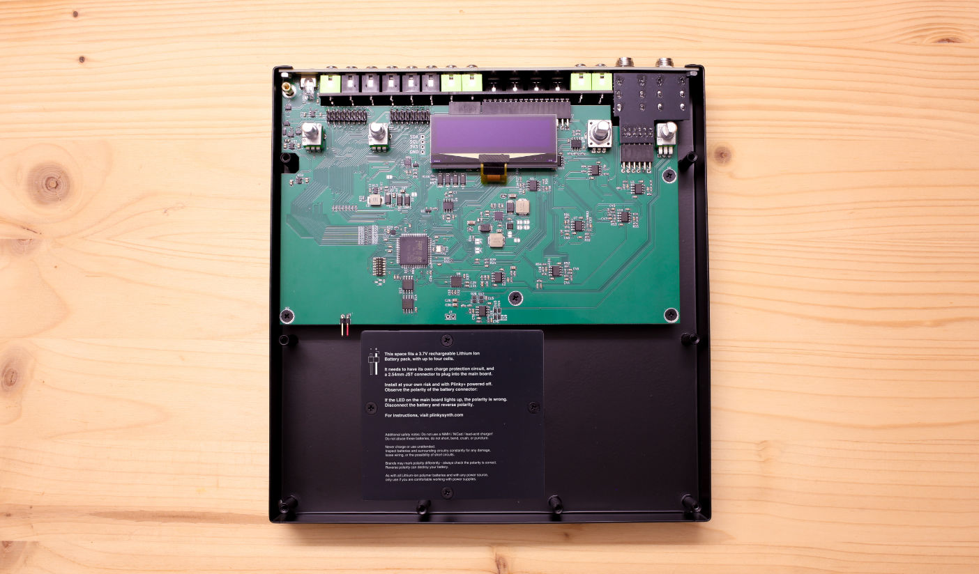
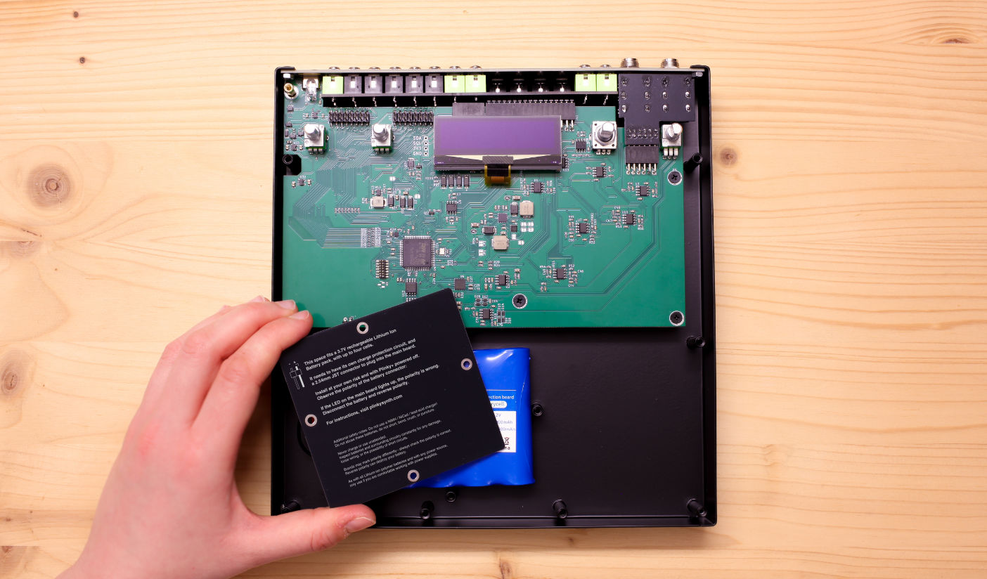
An extra PCB panel with printed safety instructions covers four welded studs that forms a cavity for a Battery Pack. Remove the four screws and lift it up.
Connect the Battery Pack
Make sure you are electrostatically discharged before you handle the PCB and Electronics. The SMD components are delicate. Handle carefully.
Make sure Plinky+'s Power on / off switch is set to off. The switch has two positions held by a click mechanism. In the off position, it sticks out further.
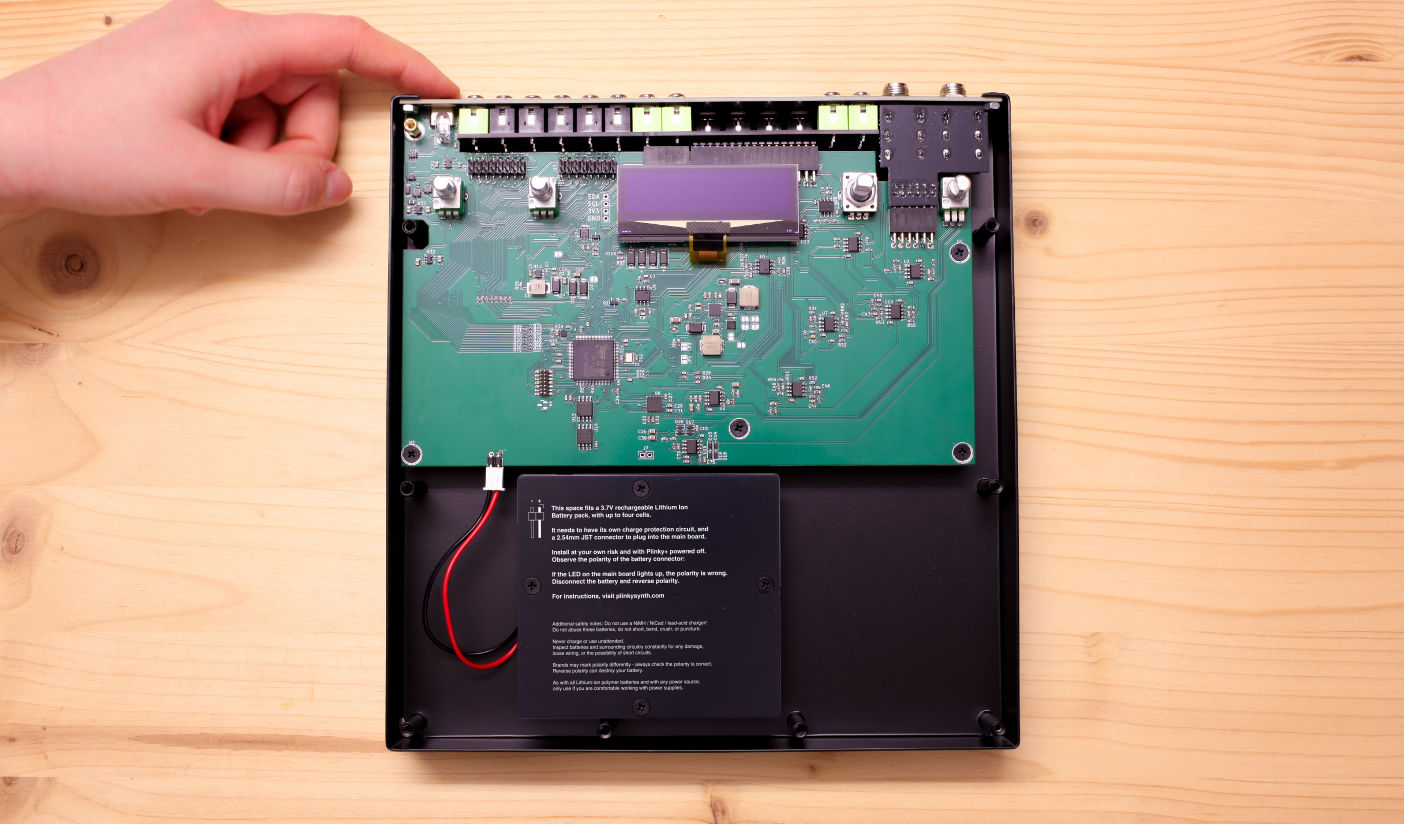
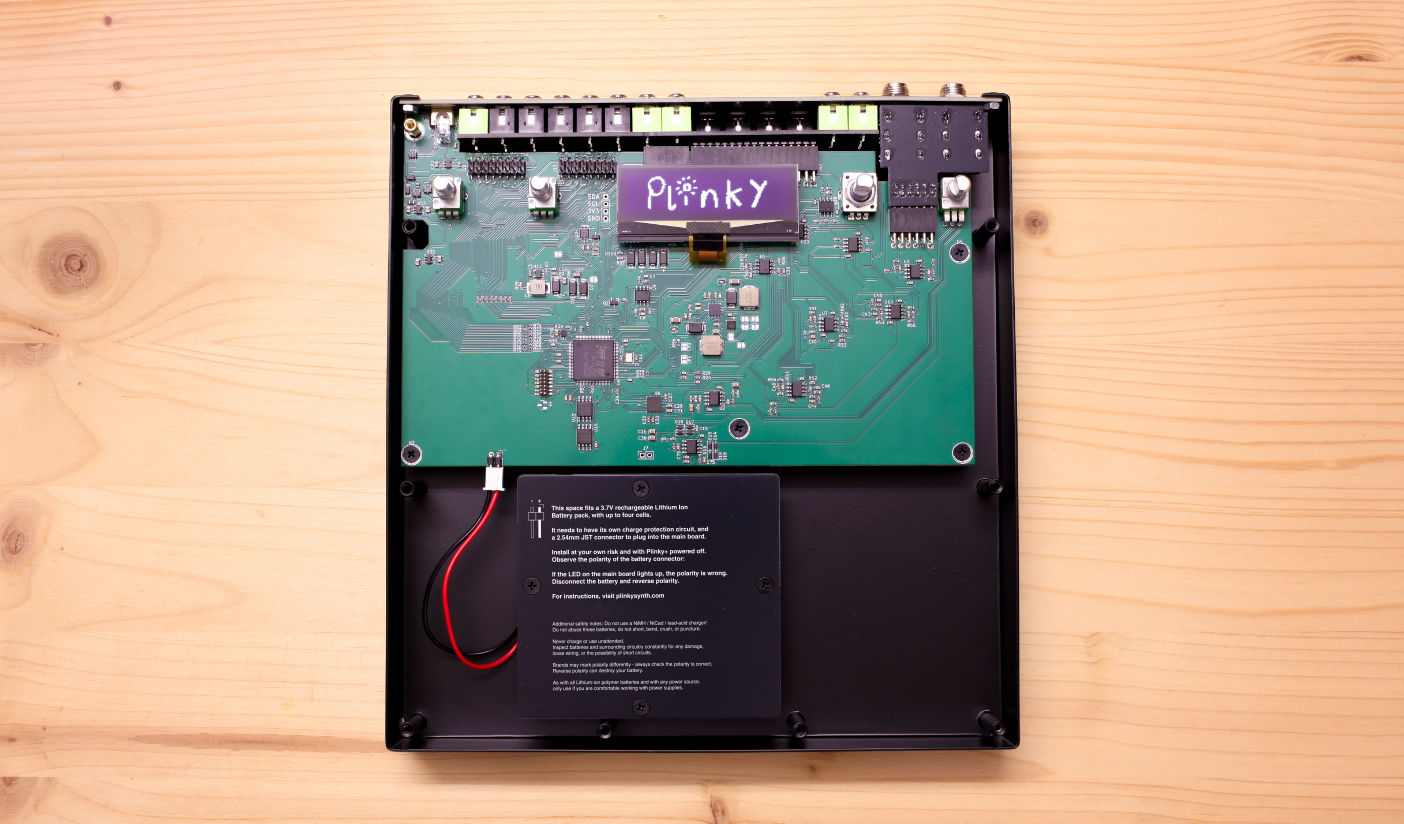
The space between the four screw posts fits a standard 3.7V rechargeable Lithium Ion Battery Pack with four 18650 cells. Place the battery in the space below the mainboard and connect the battery to the 2.45 mm pinheader on the bottom left of the mainboard.
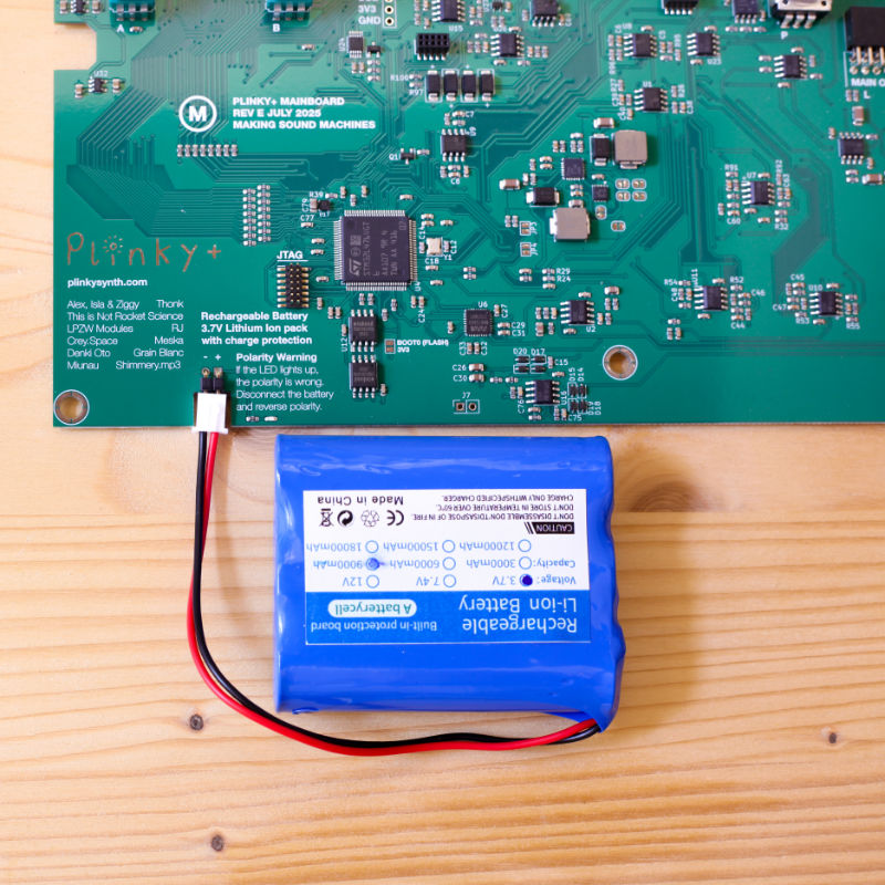
The connector on the PCB is marked Rechargeable Battery – 3.7V Lithium Ion pack with charge protection. A Polarity Warning is printed next to the pinheader.
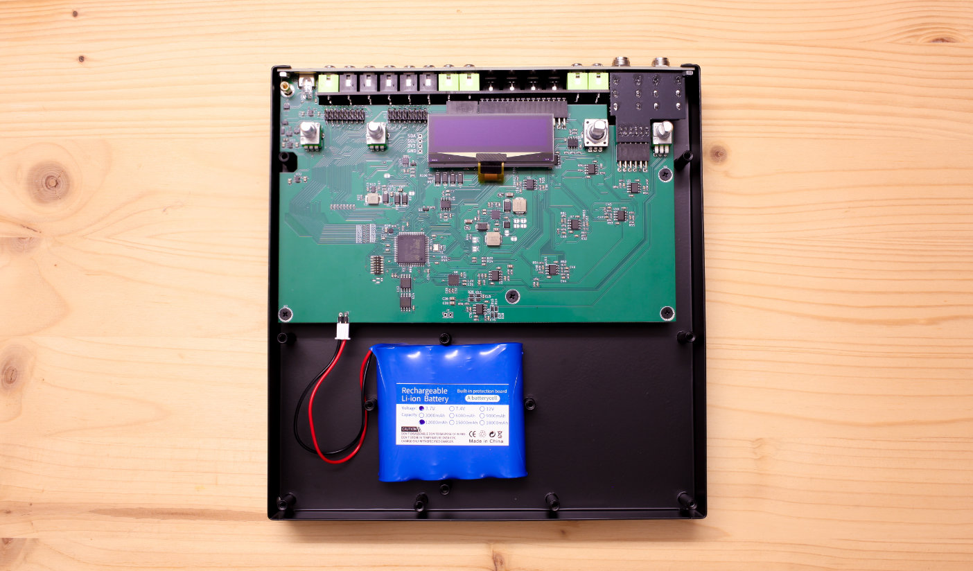
Make sure the Power Switch is in the off position, then connect the Battery. Make sure you get the polarity right: looking at the mainboard at the side with the print labels right side up, the negative terminal sits on the left side, the positive terminal on the right.
Various brands may mark polarity differently – most have a red and black cable, but what that means in terms of polarity may vary. Always check with the datasheet of your Battery Pack that the polarity is indeed correct, and matches the print on the PCB.
The LED on the board acts as a polarity test. If the LED on the main board lights up, the polarity of the Battery Pack is incorrect. In this case, disconnect the Battery's cable and reverse the polarity!
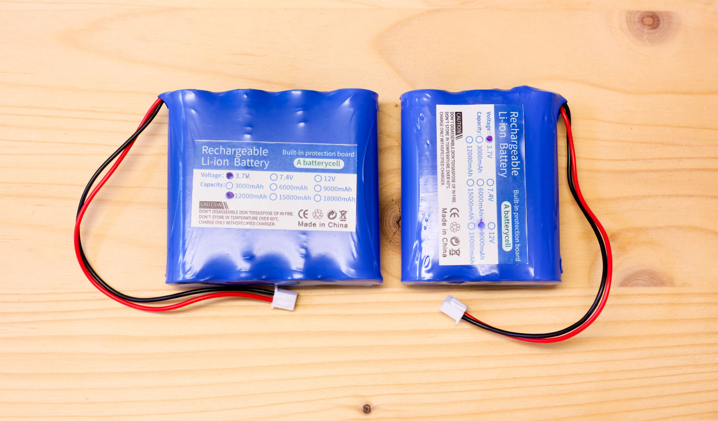
As an example, the Battery Pack pictured below has a 2.54mm connector and you verified the polarity as Black - / Red +. Now you need to match the polarity with the print on the main board and connect the JST socket to the pinheader.
Reinstall the Battery cover using the four black M3 screws.
Now, test whether Plinky+ powers up by pressing the on/off button. Once Plinky+ boots and has started up as expected, with the Plinky logo on its screen, power it off.
Reinstall the front panel with its screw and hex nuts. Push the four knob caps back on. Provided the Battery is charged, your Plinky+ is now ready to run on either Battery or USB.
If you are looking for detailed instructions on how to install the front panel or need to yet finish your build, please continue here.
Charging via USB
You can use the USB-C port to charge the Battery with a 1A rate.
Plinky+ draws about 400 mA from a 5V supply. Due to the relatively large capacity of common Lithium Ion Battery Packs, you may be able to use Plinky+ for a long time on a single full charge – we tested up to 8 hours in one go, with a four cell Battery Pack.
But a large capacity for the Battery also means a full charge may take a long time. At a 1A rate, a full charge may take around 11 hours.
The USB window will glow red while the Battery is charging, and switches to blue once fully charged.
Charge Rate
When charging Lithium batteries, it's important to keep track of the charge rate. A rule of thumb is, you should max charge at 1C of current. For a 9000mAh Battery Pack, it's 9000mA. Plinky+ charges at a 1000mA rate. This means you cannot use a Battery smaller than 1000mAh.
You can estimate how long it takes to charge a battery by taking the capacity, dividing by the rate, and multiplying by 125%.
For example, a 9000mAh battery charging at 1000mA takes 9000/1000 * 125% = 11 Hours. Less if the Battery is not fully drained!
Additional Safety Notes
Do not abuse these types of Battery Packs, do not short, bend, crush, or puncture. Never charge or use them unattended.
While installing, inspect the Battery and surrounding circuitry for any signs of damage, loose wiring, or the possibility of short circuits.
Various brands may mark polarity differently –always check the polarity is correct. Reverse polarity can destroy your battery.
Only purchase Battery Packs from sources you trust. If the Battery Pack looks defective, punctured or otherwise broken, discard it responsibly and according to applicable laws.
As with all Lithium-ion polymer batteries, and power supplies in general, only proceed with their installation if you are comfortable and experienced working with power supplies.
If in doubt, ask an expert for help, or contact us on the Plinky Discord.
Firmware
Plinky+ ships with firmware 0.B3 or higher.
Install firmware
Here are the steps required to update your firmware to the latest build:
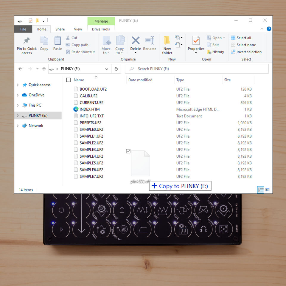
- Download the latest .UF2 file from the Firmware page.
- With Plinky+ powered off, connect Plinky+ to a power source (PC or Mac USB port, or USB power adapter)
- Hold down the Encoder, and with it held down, press the on/off button to turn Plinky+ on
- The screen remains blank, and you’ll see a tunnel of flashing LEDs
- Plinky should show up on your PC as a USB Drive
- Drag and drop the UF2 file onto the Plinky USB Drive

Safety Instructions
In Compliance with GPSR EU Regulation 2023/988, find the Safety Instructions here.